
INDIVIDUAL ATTACHMENT GUIDE
Augers
Drive units, bit types, carrier compatibility, hydraulics, torque, drilling depth, operating technique and maintenance.
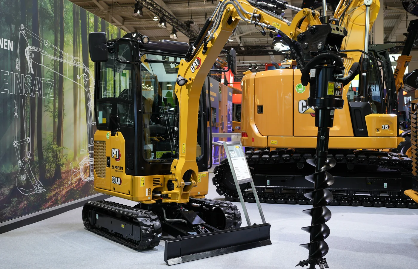
An auger attachment converts hydraulic or mechanical power into controlled rotary drilling. The correct system must match the carrier, mounting interface, oil flow, pressure, required torque, hole diameter, depth and the ground that must be cut.
NAVIGATE THE GUIDE
Choose the right auger system
Use these sections to compare the drive, bit, carrier and drilling conditions as one complete system. An auger that fits the coupler can still be unsuitable if the hydraulic circuit, torque or bit geometry is wrong.
SECTION 1
Auger types
Compare earth, rock, tree, tapered, continuous-flight and specialist drilling tools.
SECTION 2
Carrier match
Check machine capacity, mounting geometry, output shaft, working radius and stability.
SECTION 3
Hydraulics
Understand the relationship between flow, pressure, torque, speed, return pressure and case drain.
SECTION 4
Diameter and depth
Select realistic hole size, cutting diameter, bit length, extensions and spoil-clearing method.
SECTION 5
Applications
Review fencing, planting, utilities, footings, signs, foundations and agricultural work.
SECTION 6
Operation and maintenance
Drill vertically, control downforce, avoid side loading and maintain the teeth, drive and hoses.
HOW AN AUGER WORKS
Rotary torque cuts the ground and flighting removes spoil
The drive unit rotates the auger through an output shaft. A pilot point centres the tool, the cutting teeth loosen the ground and the helical flighting carries spoil upward. Productivity depends on keeping the tool vertical, maintaining a controlled rotation speed and allowing the flighting to clear material rather than packing it into the hole.
- Drive unit: converts hydraulic flow and pressure, PTO power or another power source into rotation and torque.
- Mounting frame or cradle: connects the drive to the carrier and normally allows the bit to hang vertically.
- Output shaft: transfers torque to the bit through a hexagonal, round or manufacturer-specific connection.
- Pilot point: starts the hole, stabilises the bit and helps the cutting teeth follow the intended centreline.
- Cutting teeth: penetrate soil, clay, gravel or rock and must be selected for the material and duty.
- Flighting: transports loosened material upward and determines how effectively spoil leaves the hole.
- Extensions: increase drilling depth but also increase mass, leverage, clearance requirements and handling risk.
DRIVE UNIT AND MOUNTING
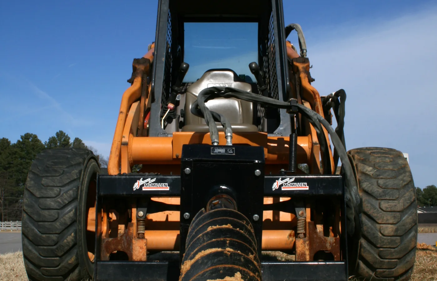
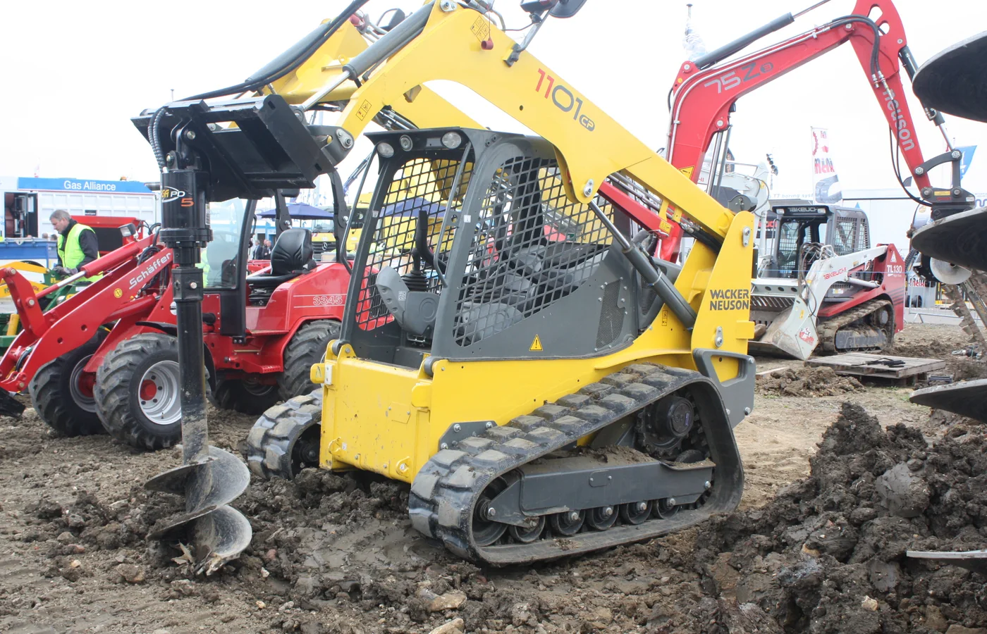
The drive is selected by torque, speed and carrier hydraulics
Small light-duty systems may use a hydraulic motor with relatively simple reduction. Higher-torque systems normally use planetary reduction, and demanding rock or large-diameter work may require double reduction, high-flow hydraulics or a two-speed drive. The published torque rating is only useful when the carrier can supply the specified pressure and flow.
- Direct or low-reduction drives: compact and economical for smaller holes and easier ground, but with less multiplication of torque.
- Single planetary drives: a common all-round solution that balances useful bit speed with increased output torque.
- Double planetary drives: provide greater reduction and torque for larger bits, dense material and heavier carriers.
- Two-speed drives: allow faster rotation for small easy holes and lower-speed, higher-torque operation for larger or harder drilling.
- Pendulum or self-aligning cradles: help the bit hang vertically when the carrier is not perfectly level, but do not replace correct setup.
- Fixed mounts: provide more controlled positioning in some specialist applications but demand accurate carrier alignment.
AUGER AND BIT TYPES
Match the cutting system to the ground
Bit diameter is only one part of the choice. The pilot, cutting teeth, flight thickness, pitch and wear protection determine how the tool penetrates and carries spoil. A general-purpose earth bit can perform poorly or suffer rapid wear when used in cobbles or rock.
EARTH
General-purpose earth augers
Designed for common soils such as loam, sand and cultivated ground. Replaceable earth teeth and a central pilot make them suitable for routine post, sign and planting holes.
CLAY
Heavy-duty clay augers
Use robust flighting and cutting geometry intended to keep cutting in cohesive material. Sticky clay may still require slower rotation and frequent spoil clearing.
ROCK
Rock augers
Use wear-resistant pilots and teeth arranged to cut fractured or hard material. They need sufficient torque and should not be confused with a true core barrel.
PLANTING
Tree and root-ball augers
Often use tapered or specialised shapes to prepare planting holes, loosen sidewalls or create space for root systems.
SPECIALIST
Continuous-flight augers
Extended flighting can transport spoil over a greater length and is used in selected foundation, sampling and specialist drilling systems.
HARD MATERIAL
Core barrels and drilling tools
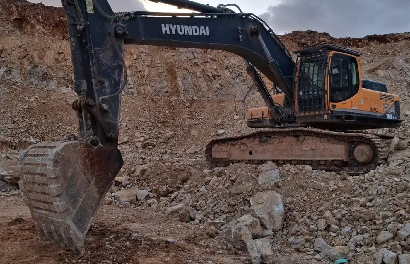
Core barrels cut an annular path and can isolate a central core in competent material. They require a compatible drive, teeth and operating method.
GROUND CONDITIONS
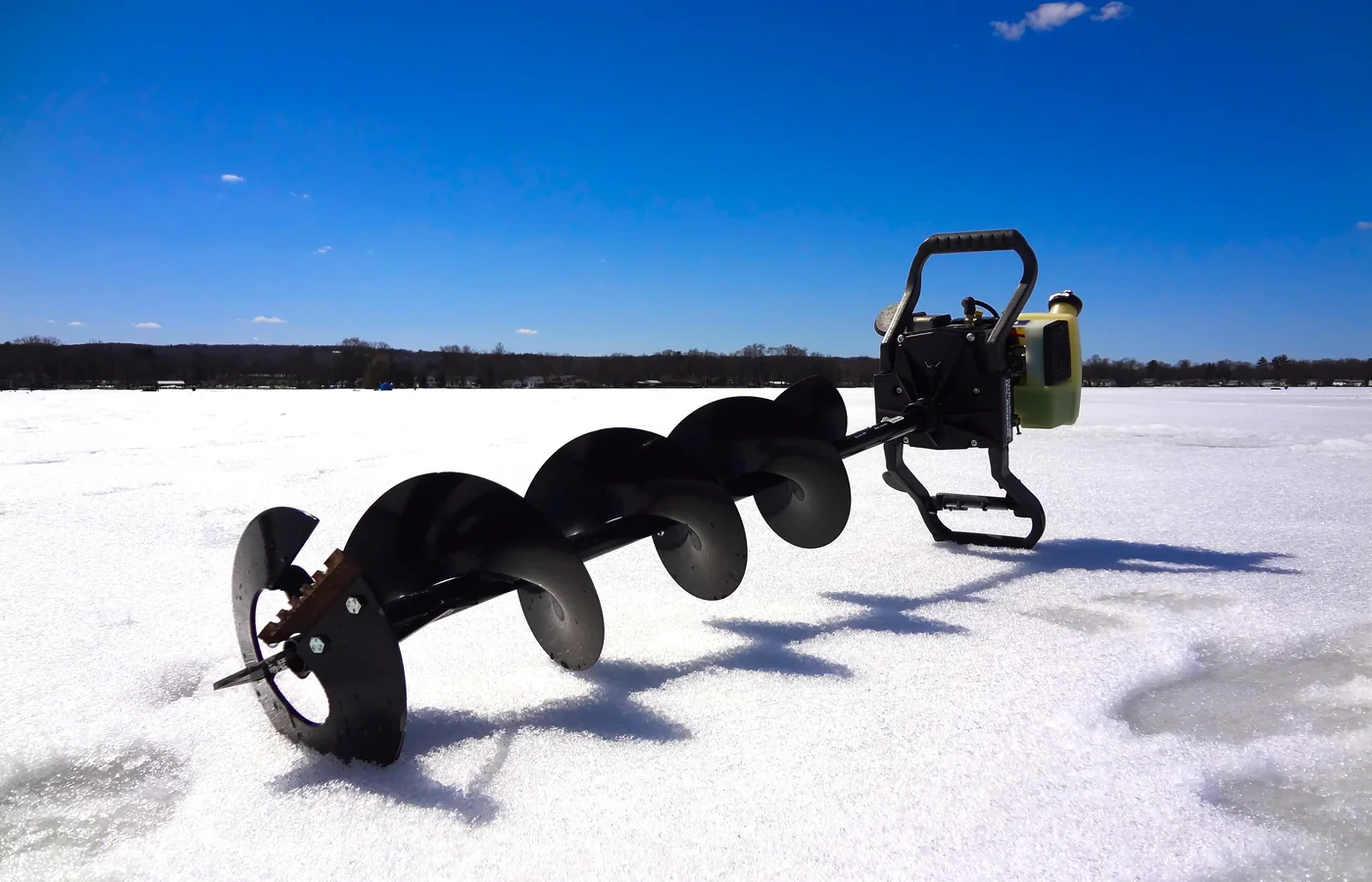
Soil behaviour controls penetration and spoil removal
The same auger can behave very differently as moisture, compaction and inclusions change. Before selecting the attachment, identify the hardest expected layer rather than only the topsoil visible at the surface.
- Loose sand and dry soil: usually cut easily, but the hole can collapse and loose spoil may fall back after withdrawal.
- Loam and mixed soil: generally suitable for standard earth bits if roots, stones and buried debris are limited.
- Dense clay: demands more torque and can adhere to the flighting. Excessive speed may polish the hole instead of clearing it.
- Wet sticky material: can bridge between flights and increase extraction load. Clean the bit only with the machine safely isolated.
- Gravel and cobbles: may deflect the pilot, jam between flights or require a stronger tooth and pilot arrangement.
- Fractured rock: needs rock teeth, controlled speed and sufficient torque. Large fragments must be cleared without forcing the bit sideways.
- Competent hard rock: may require a rock auger, core barrel, down-the-hole equipment or a different drilling method entirely.
- Made ground and demolition fill: can contain steel, timber, concrete and utilities. Investigate before drilling and expect unpredictable loading.
CARRIER COMPATIBILITY
Match the complete installed system
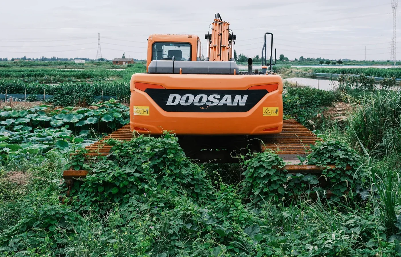
Do not select an auger only by carrier tonnage or coupler type. The drive, mounting frame, hoses, adapter, bit and any extension all add weight and move the load away from the machine. The carrier must safely position, rotate, extract and transport the complete system.
- Approved carrier range: use the attachment manufacturer’s permitted machine class and application limits.
- Mounting interface: confirm pin dimensions, quick-coupler profile, skid-steer plate, three-point linkage or specialist bracket.
- Lift and stability: include the drive, bracket, longest intended bit, extension and the spoil carried on the flighting.
- Output shaft: verify shaft shape, size, locking pin and the torque capacity of every adapter in the connection.
- Working envelope: check boom, dipper, linkage and hose clearance with the auger vertical, swinging and fully raised.
- Carrier position: confirm the machine can remain level and stable at the intended reach without relying on unsafe side loading.
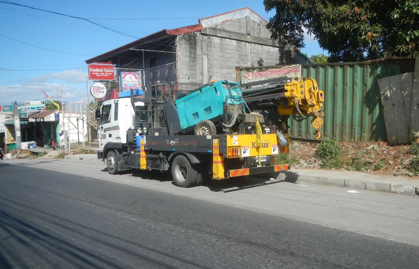
- Transport: long bits and extensions may need to be removed and secured separately rather than carried beneath the boom.
HYDRAULIC REQUIREMENTS
Flow sets speed; pressure makes torque available
Hydraulic flow largely determines rotational speed, while working pressure enables the drive to produce torque against resistance. A carrier with high flow but insufficient pressure may spin quickly in easy soil and stall in dense ground. A high-pressure circuit with excessive flow may overspeed the bit, create heat and accelerate wear.
- Flow range: keep the carrier’s actual auxiliary flow inside the drive manufacturer’s permitted range.
- Pressure and relief setting: confirm the operating pressure and set the relief according to the attachment specification.
- Torque requirement: choose enough torque for the largest bit and hardest expected material, not only the easiest holes.
- Rotation speed: use a controlled speed that lets the teeth cut and the flighting carry spoil without throwing material.
- Return pressure: restricted couplers, undersized hoses and long return paths can reduce performance and damage the motor.
- Case drain: some motors require a dedicated low-pressure drain. Never plug or tee it into an unsuitable return line.
- Reversible flow: useful for clearing a jam or releasing the tool, but only when the drive and bit are designed for reverse operation.
- Oil cleanliness and cooling: contaminated or overheated oil shortens motor, seal and valve life.
DIAMETER, DEPTH AND EXTENSIONS
A larger or deeper hole changes every load in the system
Increasing diameter raises the cutting area, spoil volume and torque demand. Increasing depth adds bit mass, extension joints and leverage while reducing visibility and control. Select from the manufacturer’s approved diameter and extension combinations rather than assuming any bit that fits the shaft can be used.
- Finished diameter: allow for material relaxation, hole collapse, casing or the clearance required around a post, footing or plant.
- Bit length: distinguish overall tool length from the maximum achievable hole depth below the working surface.
- Extensions: add depth in controlled stages and confirm each connection, locking pin and lifting method.
- Spoil capacity: deep or large-diameter holes may require several withdrawal cycles to clear the flighting.
- Hole straightness: start slowly with the pilot centred, verify vertical alignment from two directions and correct early.
- Extraction load: wet clay and packed spoil can make lifting the auger harder than drilling downward.
- Clearance: ensure the carrier has enough boom height to withdraw the full bit and extension without contacting the machine or overhead hazards.
COMMON APPLICATIONS
Where auger attachments are used
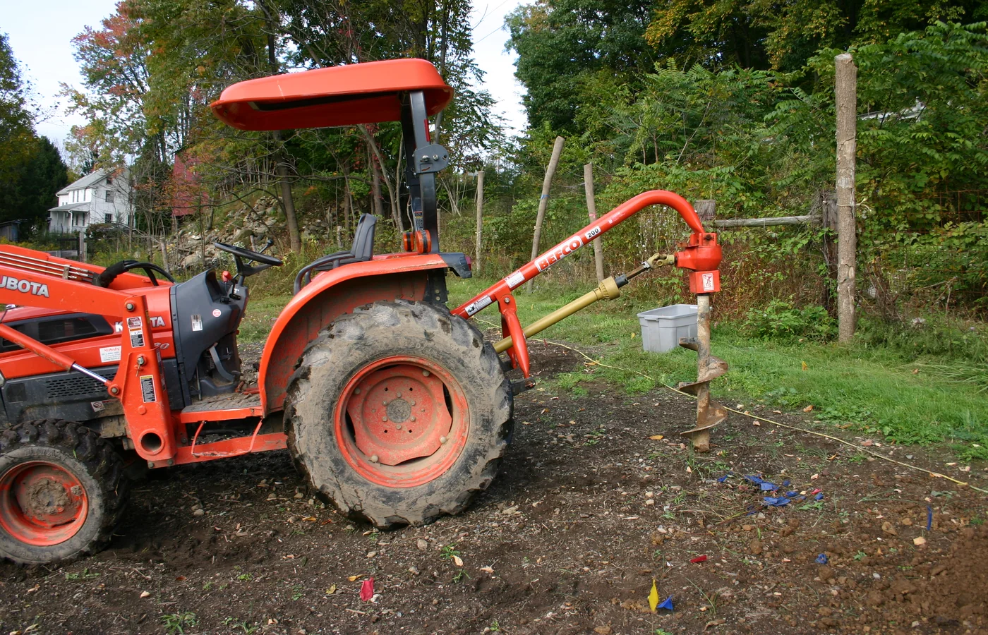
Augers create controlled circular holes with less excavation than a bucket. Their value is highest when the hole diameter, location and depth are repeatable and when spoil can be safely removed from the work area.
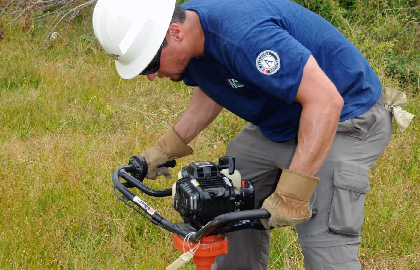
Fencing, gates and signs
Fast repetitive holes for fence posts, gate supports, traffic signs and site furniture. Confirm the required clearance, embedment and ground condition before choosing the bit.
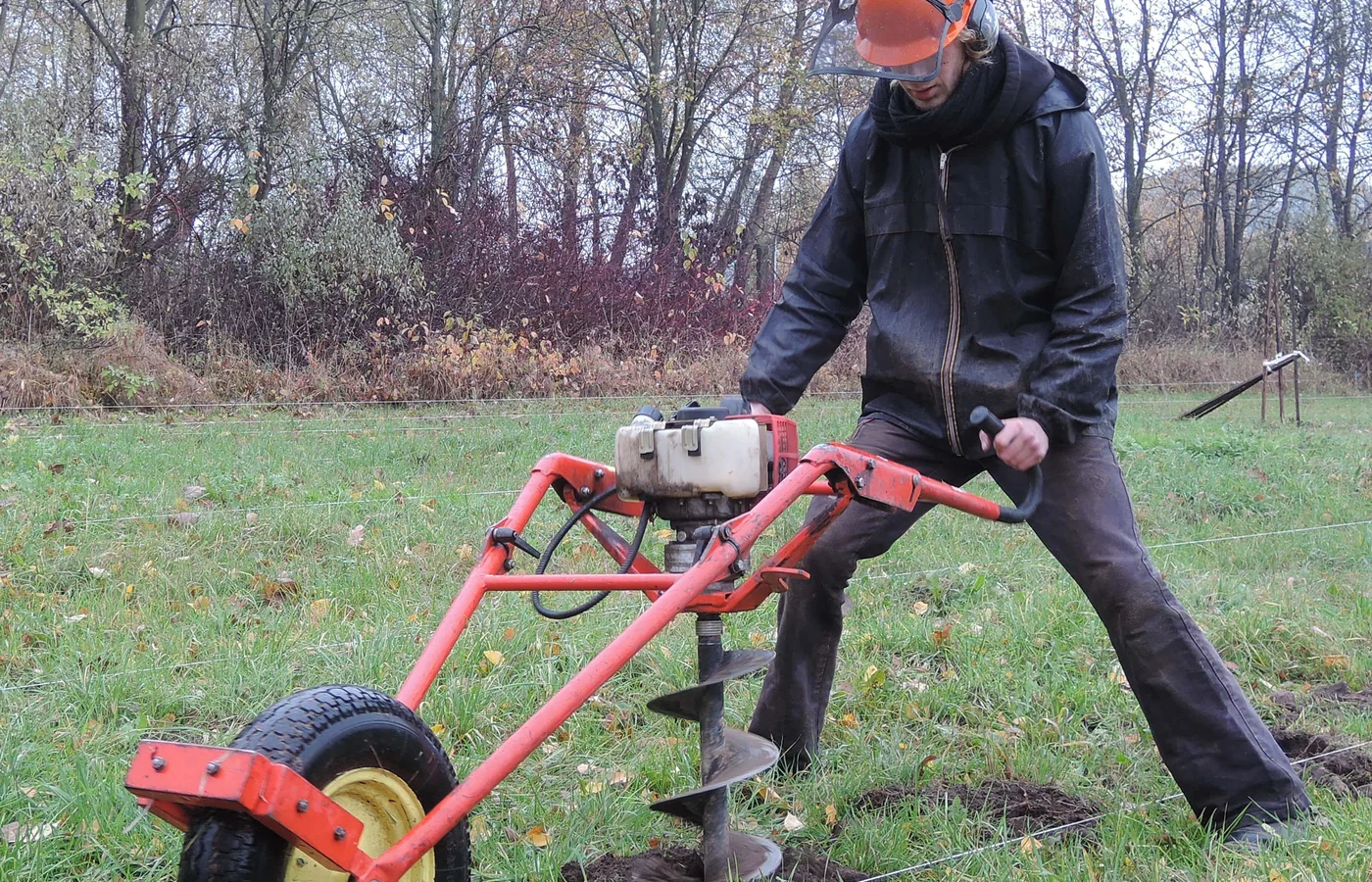
Tree and shrub planting
Planting augers can prepare consistent holes for landscaping and afforestation. Avoid glazing clay sidewalls and size the hole for the root system and soil preparation method.
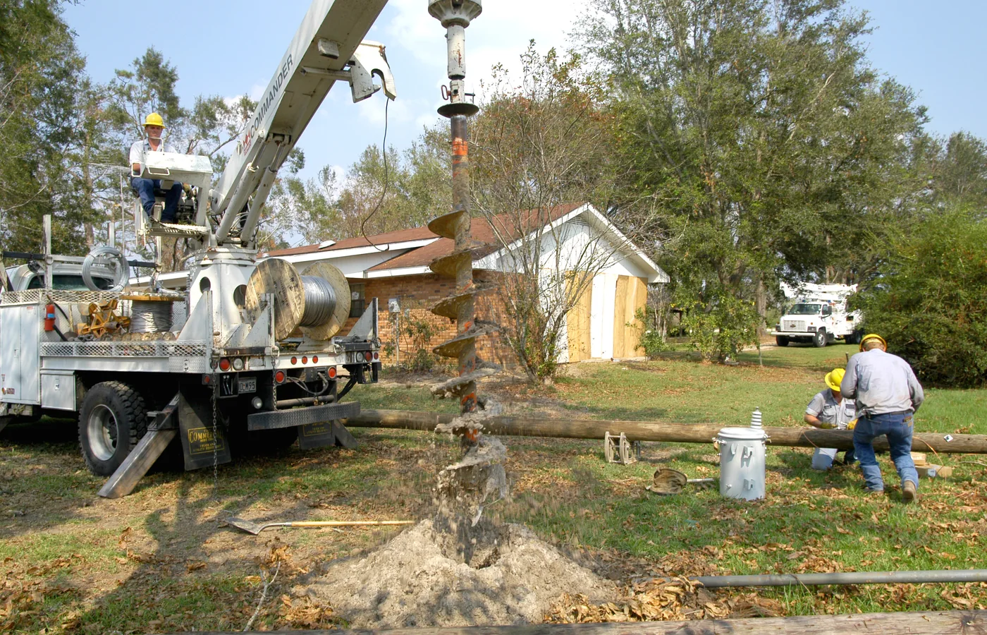
Utility poles and services
Used for poles, columns and selected utility structures. Underground-service location, exclusion zones and overhead-line clearance are essential.
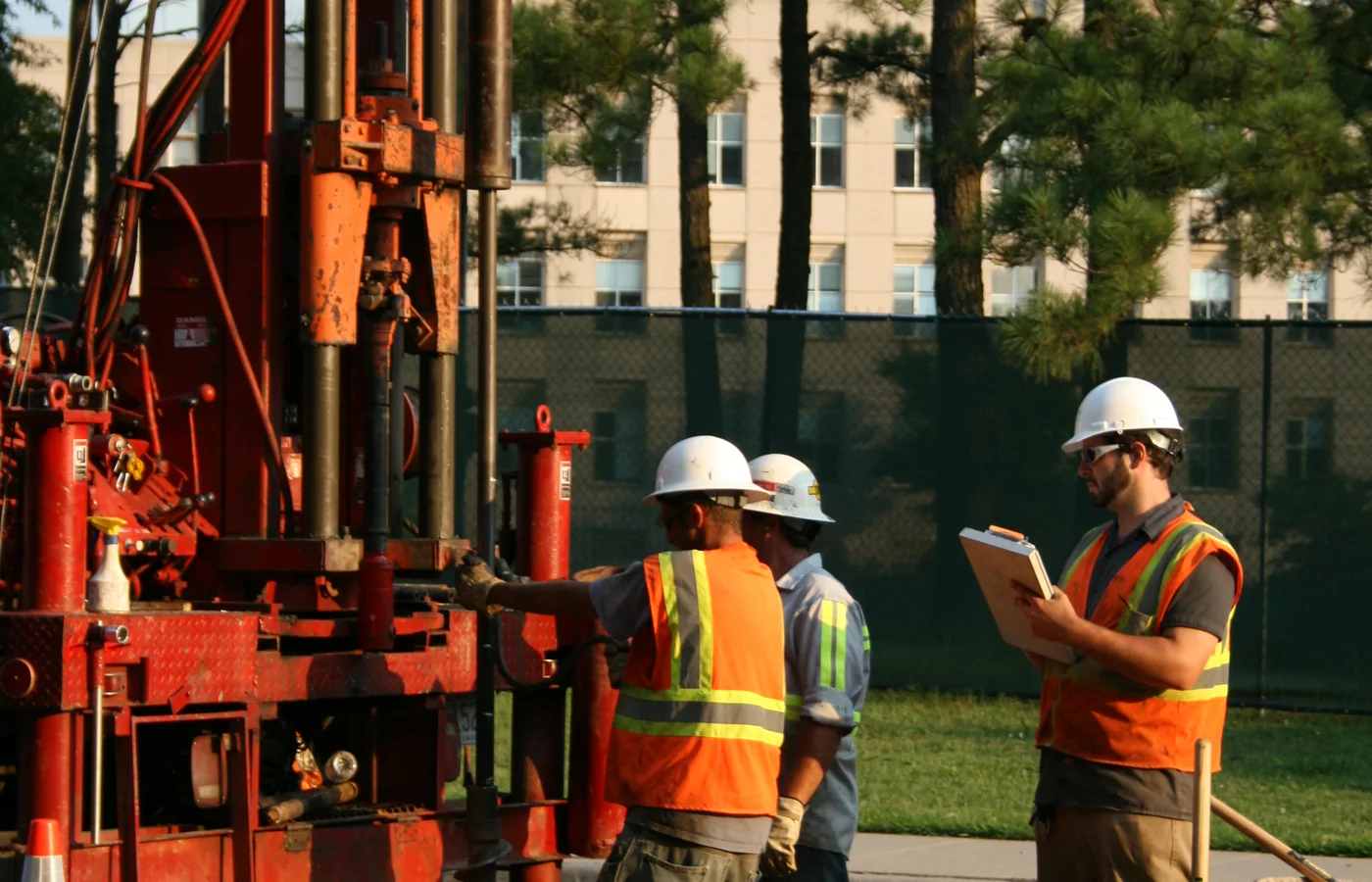
Footings and foundations
Augers can prepare holes for small footings, piers, anchors and specialist foundation systems. Structural work requires the specified diameter, depth, cleanliness and inspection.
OPERATING TECHNIQUE
Drill straight, clear spoil and avoid side loading
The operator should follow the attachment and carrier manuals, but the same basic principles apply to most earth augers. Correct technique protects the output shaft, gearbox, bit and carrier linkage while producing a cleaner hole.
START
1. Prepare and locate
Confirm utility clearance, mark the centre, establish the exclusion zone and position the carrier on stable ground.
ALIGN
2. Align vertically
Lower the pilot to the mark and check plumb from the cab and, where safe, from a second viewing direction.
CUT
3. Start slowly
Begin at controlled speed so the pilot establishes the centre without skating or pulling the bit sideways.
LOAD
4. Use steady downforce
Let the teeth cut. Excessive crowd force can bend the bit, overload the shaft or make the carrier unstable.
CLEAR
5. Clear spoil regularly
Raise the rotating bit only as permitted and clear the flighting before packed material increases extraction load.
FINISH
6. Finish and withdraw
Clean the bottom as required, stop rotation before travel and secure or remove long tools for transport.
COMMON SELECTION AND OPERATING MISTAKES
What causes poor drilling performance
Many auger problems are caused by the system match or operating method rather than a defective drive. Correct the cause before replacing parts or increasing pressure.
MISTAKE 1
Too much speed
High rpm can throw spoil, polish clay, increase vibration and prevent the teeth from taking a controlled cut.
MISTAKE 2
Too little torque
The bit repeatedly stalls when diameter or ground resistance exceeds the drive and available hydraulic pressure.
MISTAKE 3
Wrong teeth for the ground
Earth teeth wear rapidly in rock, while aggressive rock tooling may be inefficient in loose soil.
MISTAKE 4
Drilling out of plumb
Correcting late side-loads the shaft and produces an oversized, curved or unstable hole.
MISTAKE 5
Overpacked flighting
Failing to clear spoil increases extraction force and can trap the bit in cohesive material.
MISTAKE 6
Unapproved extensions
Long tools and improvised adapters increase leverage and can exceed shaft, mount and carrier limits.
SAFETY
Control underground, rotating and stability hazards
An auger combines a powerful rotating tool with hidden ground conditions. Site planning is therefore as important as the attachment selection. Follow local rules, the carrier manual and the auger manufacturer’s instructions.
- Locate underground services: obtain current utility information, scan or expose as required and respect the marked tolerance zone.
- Maintain an exclusion zone: nobody should stand near a rotating bit, suspended extension or spoil being discharged.
- Prevent entanglement: never approach, clean or handle flighting while the attachment can rotate. Isolate and relieve stored energy first.
- Check overhead clearance: long augers, booms and utility work can approach power lines, structures and tree canopies.
- Use stable ground: level the carrier, respect load charts and avoid drilling where the machine could slide, tip or undermine itself.
- Handle extensions safely: use approved lifting points and methods; never rely on a person to steady a suspended tool.
- Control ejected material: stones, metal and compacted spoil can leave the flighting unexpectedly.
- Inspect the hole: protect open holes from people, animals, vehicles, water ingress and collapse until the work is completed.
MAINTENANCE AND INSPECTION
Keep cutting parts sharp and the drive correctly supported
A worn pilot or tooth changes drilling accuracy and increases torque demand. Inspection should cover the complete load path from the carrier coupler to the bit point.
DAILY
Before each shift
Inspect the mount, pins, locking devices, hoses, couplers, leaks, output shaft, bit connection, pilot and teeth.
MONITOR
During operation
Watch for unusual noise, heat, vibration, oil leakage, slow rotation, repeated stalling or a bit that no longer hangs freely.
SERVICE
Scheduled service
Lubricate specified pivots, change gearbox oil at the required interval and inspect seals, bearings and motor case-drain condition.
WEAR PARTS
Cutting system
Replace missing or rounded teeth and a worn pilot before the tool demands excessive downforce or begins wandering.
BIT
Bit and flighting
Check cracks, bent centre tubes, damaged flight edges, worn welds and packed material. Remove damage using approved repair procedures.
PROTECTION
Storage and transport
Clean the tool, cap hydraulic connections, support the drive and store long bits where they cannot roll, fall or collect water.
SELECTION CHECKLIST
Information to collect before choosing an auger
A useful quotation request should describe the carrier and the drilling task. This allows the supplier to select the drive, mount, shaft, bit and teeth as one approved combination.
- Carrier: make, model, operating weight, boom or lift-arm configuration and any quick coupler or tilt system.
- Hydraulics: measured or published auxiliary flow, maximum pressure, relief setting, return arrangement and case-drain availability.
- Mount: pin centres and diameters, coupler profile, skid-steer interface, three-point category or specialist connection.
- Hole: required finished diameter, depth, quantity, spacing, permitted tolerance and whether extensions are needed.
- Ground: soil report or realistic description of clay, sand, gravel, cobbles, roots, fill, fractured rock and groundwater.
- Application: fencing, signs, planting, poles, footings, anchors, sampling or specialist foundation work.
- Site constraints: access width, overhead clearance, underground utilities, slope, noise, transport and spoil handling.
- Duty cycle: occasional holes, repeated production drilling or continuous heavy-duty use.
- Required accessories: hoses, couplers, extensions, cradles, adapters, spare teeth, pilots and approved lifting equipment.
FREQUENTLY ASKED QUESTIONS
Auger attachment FAQ
Can the same auger be used on an excavator and a skid steer?
Sometimes the drive unit can be adapted between approved carriers, but the mounting frame, hose arrangement, hydraulic flow and machine stability must all be verified. An adapter plate alone does not confirm compatibility.
Does more hydraulic flow create more drilling power?
More flow mainly increases rotation speed. Available torque depends strongly on pressure, motor displacement and gearbox reduction. Excess flow can overspeed the drive and create heat without solving a torque shortage.
Which auger is best for rock?
Use a rock-rated bit, pilot and tooth system matched to the hardness and structure of the material. Fractured rock may suit a rock auger, while competent hard rock may require a core barrel or another drilling method.
Why does an auger keep stalling?
Common causes include an oversized bit, inadequate pressure, insufficient drive torque, worn teeth, excessive downforce, packed flighting, stones or a hydraulic restriction. Stop and identify the cause rather than repeatedly shocking the drive.
How can the operator keep the hole vertical?
Set the carrier level, allow a pendulum mount to hang freely, centre the pilot and check alignment from two directions before drilling deeply. Small corrections should be made early; late corrections bend the hole and side-load the system.
Can an extension be fitted to any auger?
Only use approved extensions, pins and combinations. Extensions increase leverage, mass and extraction load and can exceed the drive shaft, mounting system or carrier working envelope.
What is the difference between an earth auger and a rock auger?
Earth augers use pilots and teeth intended for soils and easier material. Rock augers use harder wear components and cutting geometry designed to penetrate abrasive or fractured material at controlled speed and higher torque.
How often should auger teeth be replaced?
Replace teeth and the pilot when wear changes the cutting profile, increases downforce, reduces hole accuracy or approaches the manufacturer’s limit. Frequency depends on ground abrasiveness, alignment and operating technique.
CONTINUE EXPLORING
Compare augers with related digging attachments
Use the broader attachment guides to compare when a circular drilled hole is the right solution and when a bucket, trencher or other attachment is more productive.