
INDIVIDUAL ATTACHMENT GUIDE
Hydraulic Breakers
Types, carrier compatibility, hydraulic requirements, tool selection, operating technique and maintenance.
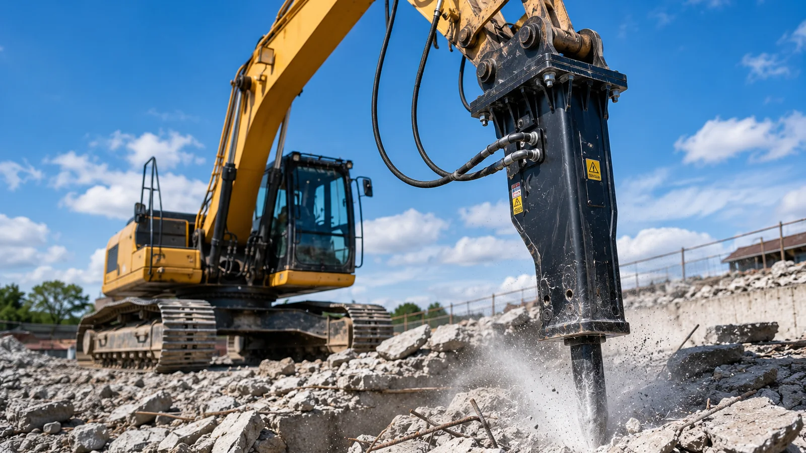
A hydraulic breaker can turn an excavator or compact loader into a productive demolition and rock-breaking machine, but only when the carrier, hydraulic circuit, mounting system and working tool are correctly matched.
NAVIGATE THE GUIDE
Find the information you need
Use the four routes below to move directly to the main technical sections.
START HERE
Breaker Types
Compare boxed, open-frame, side-mounted, top-mounted, compact and heavy-duty designs.
MATCH THE CARRIER
Compatibility
Check machine size, attachment weight, hydraulic flow, pressure, back pressure and mounting geometry.
CHOOSE THE TOOL
Working Tools
Understand moil points, chisels, blunt tools, asphalt cutters and specialist options.
PROTECT THE INVESTMENT
Maintenance
Plan greasing, bushing inspection, hose checks and operating practices that reduce avoidable wear.
OVERVIEW
How a hydraulic breaker works
The basic principle is simple, but the operating result depends on the entire carrier-and-attachment combination.
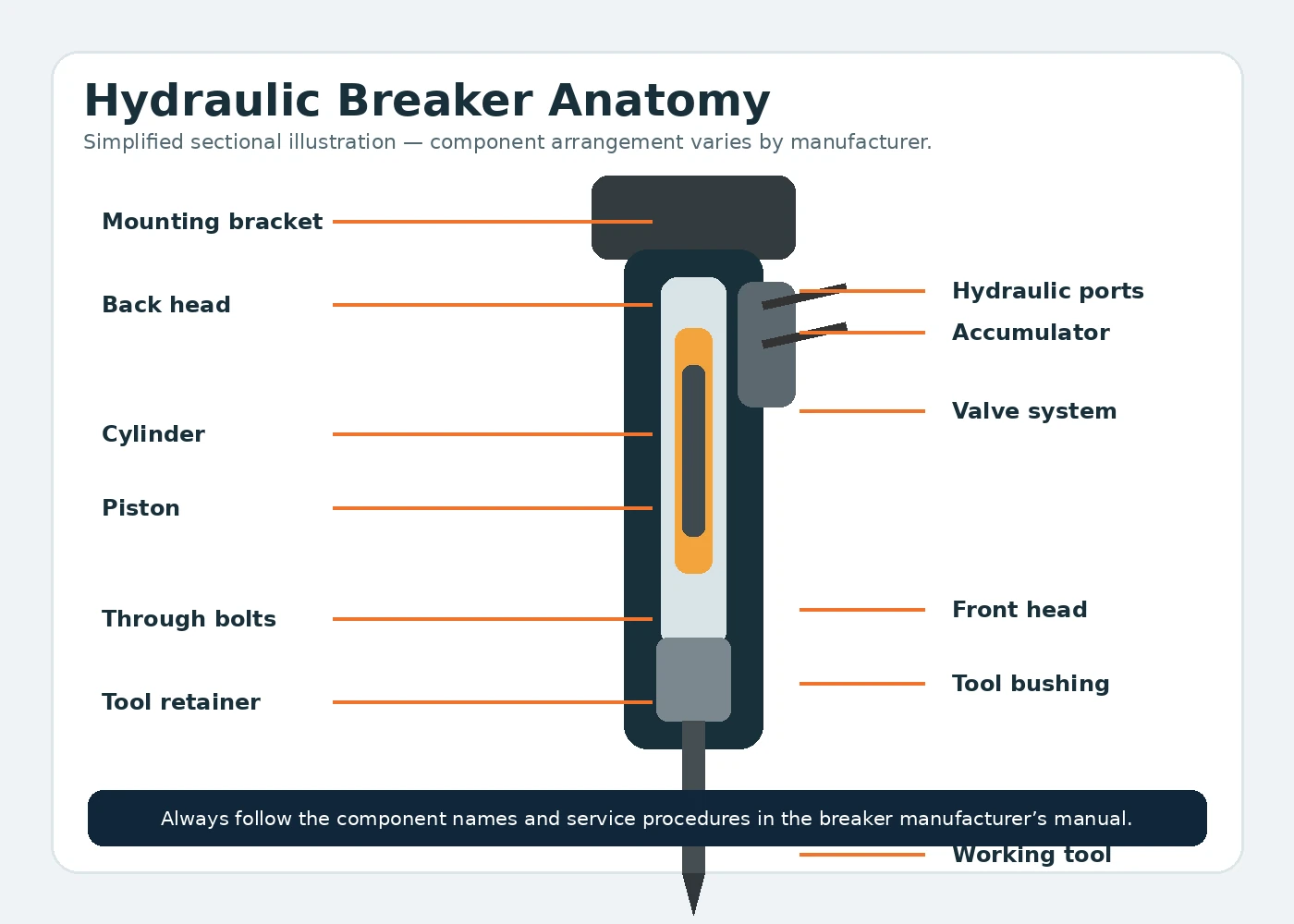
A hydraulic breaker, also called a hydraulic hammer, converts hydraulic energy from the carrier into repeated impact energy at the working tool. Oil flow drives an internal piston, which accelerates and strikes the upper end of the tool. The tool then transfers impact energy into concrete, rock, asphalt or frozen ground.
The exact internal design varies by manufacturer. Some breakers rely mainly on hydraulic pressure, while others use a combination of hydraulic power and a gas charge. The carrier does not need to understand that internal difference, but it must supply oil within the breaker manufacturer’s specified flow, pressure and return-line limits.
A breaker that physically fits the coupler can still be unsuitable. Excess attachment weight can reduce stability; incorrect flow can cause slow striking or overheating; excessive back pressure can damage seals; and poor hose routing can create repeated failures. Compatibility must therefore be checked as a complete system.
BREAKER DESIGNS
Main hydraulic breaker types
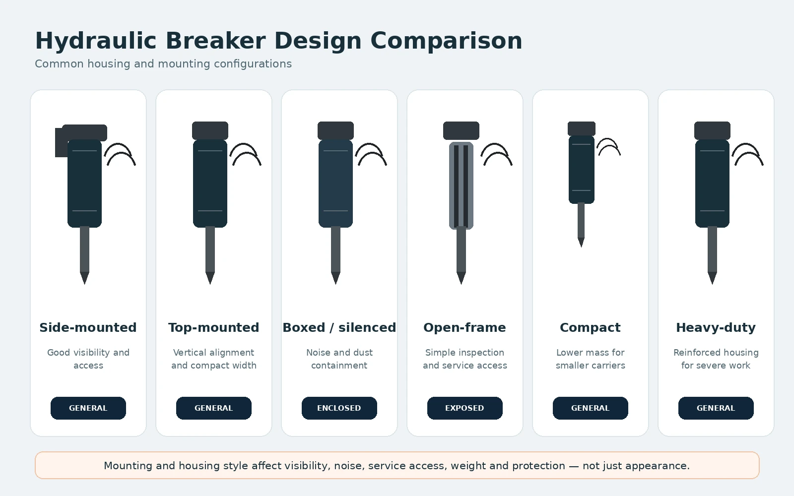
The best design depends on the carrier, working environment, noise limits, access requirements and expected duty cycle.
DESIGN
Boxed or silenced breakers
An enclosed housing can reduce external noise and protect internal components from debris. These designs are common in urban demolition, recycling and general contracting.
DESIGN
Open-frame breakers
The power cell is carried in a more open mounting frame. Access can be straightforward, but external components may have less protection from impact and contamination.
MOUNTING
Side-mounted breakers
The mounting arrangement places the bracket around the sides of the breaker body. It can offer a compact overall height and good visibility for some carriers and tasks.
MOUNTING
Top-mounted breakers
The bracket is positioned above the breaker. The geometry can suit vertical work and may make the tool easier to align with the carrier boom.
CARRIER CLASS
Compact breakers
Designed for mini excavators, compact loaders and smaller carriers. Low attachment weight, hose protection and correct low-flow matching are especially important.
CARRIER CLASS
Heavy-duty breakers
Used for quarrying, large demolition and high-production rock work. Carrier stability, mounting strength, hydraulic cooling and duty cycle become critical.
SPECIAL USE
Underwater configurations
Underwater breaking normally requires a manufacturer-approved air connection and operating procedure to prevent water and debris from entering the breaker.
SPECIAL USE
Low-noise and vibration-controlled options
Some applications prioritise reduced sound or structure-borne vibration. Breaker selection should still be based on material, carrier and productivity requirements.
CARRIER MATCHING
Hydraulic breaker compatibility
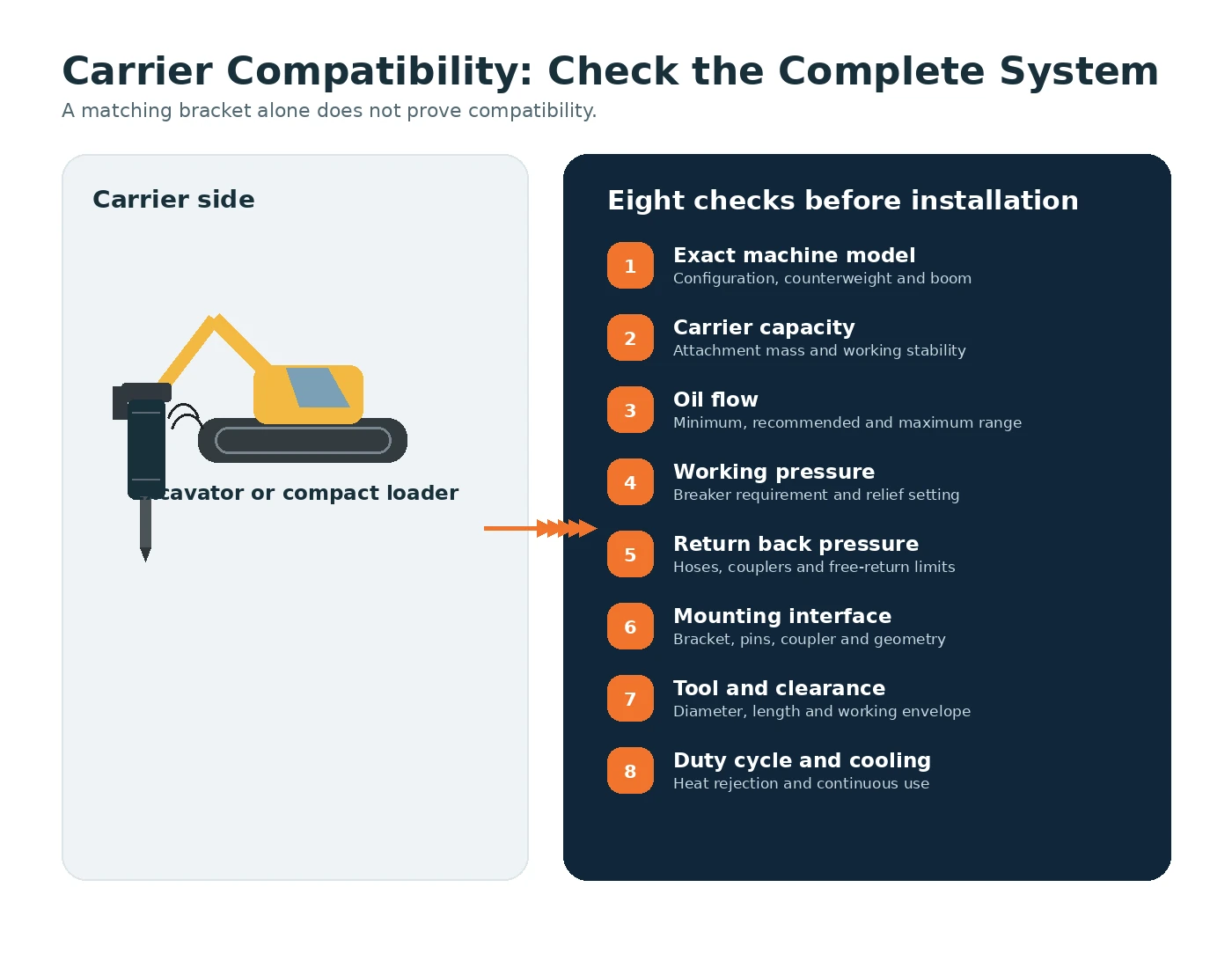
Never choose a breaker from tool diameter or impact rating alone. Verify the complete mechanical, hydraulic and operational combination. Carrier capacity, machine configuration and hydraulic performance must all be checked together.
CHECK 1
Carrier operating weight
Use the breaker manufacturer’s approved carrier range. The machine must remain stable during positioning, impact and travel.
CHECK 2
Breaker operating weight
Include the bracket, coupler, tool and any adapter components. Attachment weight reduces the carrier’s remaining lifting and stability margin.
CHECK 3
Hydraulic flow range
The carrier’s actual auxiliary flow must remain within the breaker’s permitted range. More flow is not automatically better.
CHECK 4
Working pressure
Confirm the breaker operating pressure and the carrier relief-valve setting. An incorrect setting can reduce performance or overload components.
CHECK 5
Return-line back pressure
Restricted returns, small couplers, long hoses or incorrect plumbing can create harmful back pressure and heat.
CHECK 6
Mounting interface
Check coupler type, pin diameters, centres, ear width, bracket strength and the orientation of hoses and grease points.
CHECK 7
Tool diameter and reach
Tool size affects penetration, contact area and working clearance. It should suit the breaker and the material rather than appearance alone.
CHECK 8
Cooling and duty cycle
Continuous breaking creates heat. Verify oil-cooling capacity, ambient conditions and manufacturer limits for sustained operation.
| Question | What to verify | Why it matters |
|---|---|---|
| Will the carrier remain stable? | Approved carrier range, working radius, ground conditions and attachment weight | Prevents loss of stability and excessive structural loading |
| Can the hydraulic circuit supply the breaker? | Flow, pressure, relief setting, hose size and return path | Controls impact rate, efficiency and oil temperature |
| Does the bracket fit correctly? | Coupler, pins, ear width, geometry and locking system | Ensures secure mounting and correct tool alignment |
| Can the machine control the breaker safely? | Auxiliary controls, continuous flow, return configuration and operator visibility | Supports predictable operation and safe shutdown |
| Is the application approved? | Material, duty cycle, underwater or high-temperature requirements | Avoids using a standard breaker outside its intended conditions |
HYDRAULIC CIRCUIT
Flow, pressure and return requirements
Hydraulic compatibility determines whether the breaker strikes efficiently, remains cool and avoids premature seal or component damage.
HYDRAULIC FACTOR
Oil flow
Flow strongly influences impact frequency. Too little flow may reduce production, while excessive flow can overspeed or overheat the breaker.
HYDRAULIC FACTOR
Operating pressure
Pressure must support the breaker’s cycle without exceeding its limit. Confirm the machine relief setting under real operating conditions.
HYDRAULIC FACTOR
Return back pressure
A low-restriction return is essential. Couplers, filters, valves and hose routing can all increase back pressure.
HYDRAULIC FACTOR
Hose and coupler size
Undersized hoses or restrictive couplers increase pressure loss and heat. Use the sizes and pressure ratings specified by the manufacturer.
HYDRAULIC FACTOR
Oil temperature
Repeated impact work converts energy into heat. Monitor temperature and keep coolers, filters and oil in serviceable condition.
HYDRAULIC FACTOR
Case drain or drain line
Many breakers do not use a conventional case drain, but some models or auxiliary components may require a dedicated drain or special return arrangement. Follow the exact manual.
Important: never use a generic flow or pressure value for all hydraulic breakers. The permitted range is model-specific and must be taken from the breaker manufacturer and checked against the carrier’s actual auxiliary-circuit performance.
WORKING TOOLS
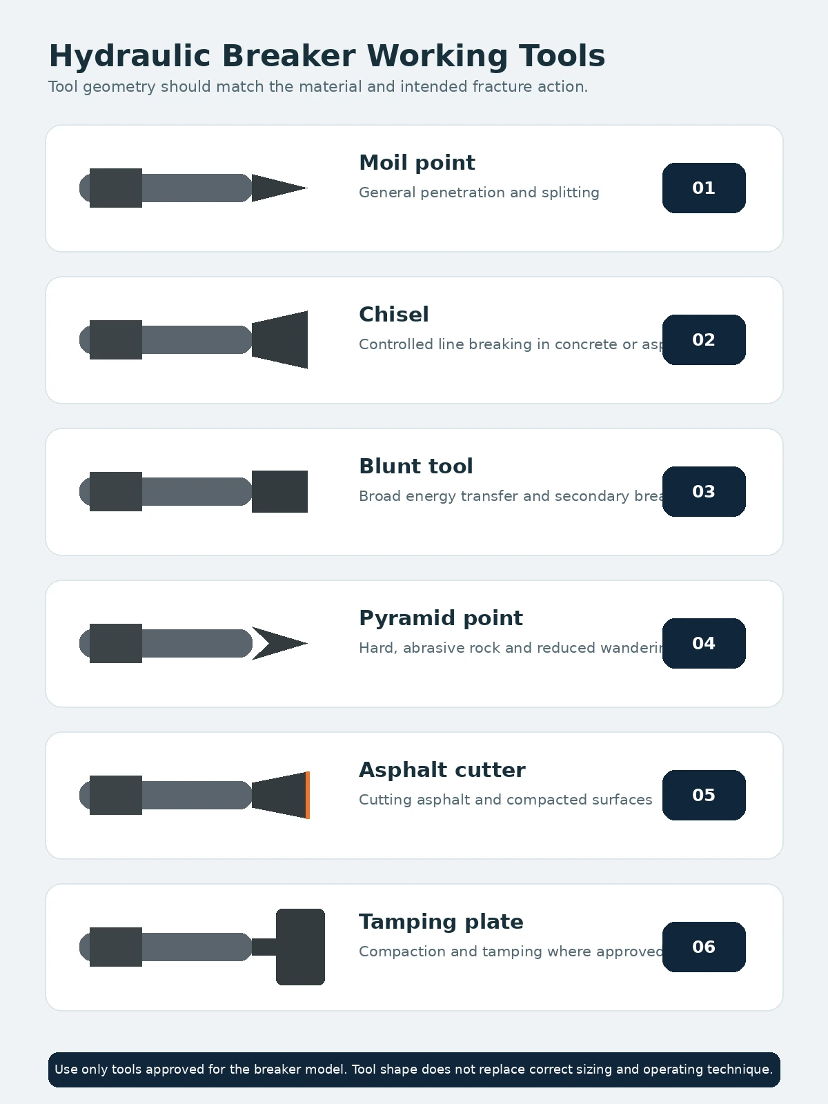
Hydraulic breaker tool types
Choose the working tool for the material and desired fracture mechanism. The tool must be approved for the exact breaker model.
WORKING TOOL
Moil point
A pointed tool for general concrete and rock breaking, trench work and applications where concentrated penetration is useful.
WORKING TOOL
Chisel tool
A flat cutting edge helps split material along a line. Chisels are used for concrete, rock, trenching and controlled breaking.
WORKING TOOL
Blunt tool
A broad end transfers impact over a larger area and is commonly used for secondary breaking of hard rock or large concrete pieces.
WORKING TOOL
Pyramid or conical point
A shaped point can combine penetration and splitting action. Availability and intended material depend on the breaker manufacturer.
WORKING TOOL
Asphalt cutter
A wide cutting edge is intended for asphalt, frozen ground and some trench-edge work. Avoid using it as a pry bar.
WORKING TOOL
Tamping or compaction plate
Some breakers can accept approved tamping tools for compacting backfill or driving posts. Verify that the breaker and tool are approved for the task.
WHERE BREAKERS ARE USED
Common hydraulic breaker applications
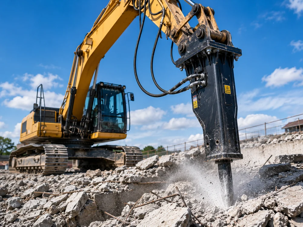
Hydraulic breakers are selected for material that must be fractured by repeated impact rather than cut, grabbed or excavated directly. The related-guides section near the end of this page connects the breaker to relevant machine, category and application pages.
APPLICATION
Concrete demolition
Break slabs, walls, foundations and reinforced structures before sorting and processing the debris.
APPLICATION
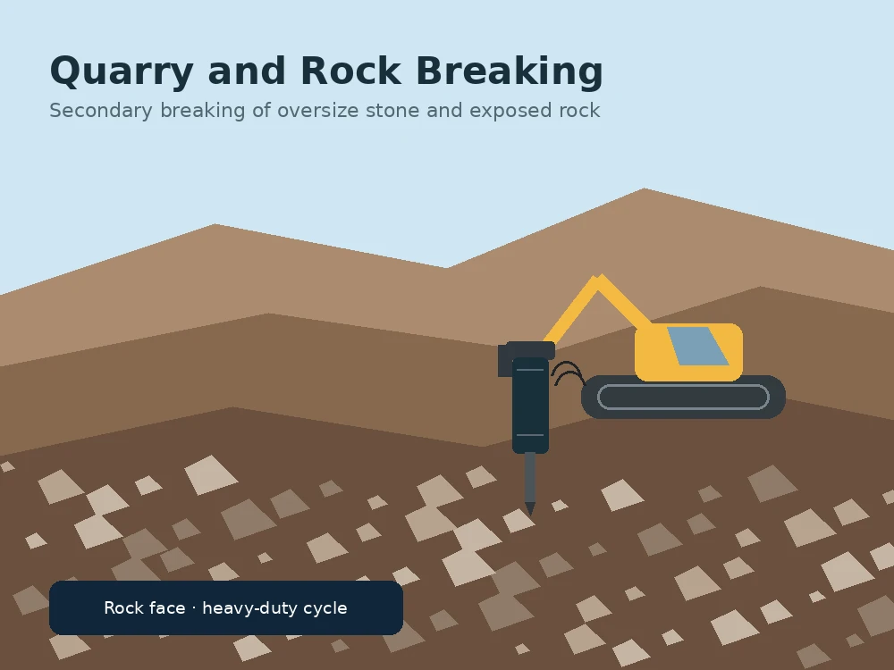
Rock breaking
Reduce oversize rock, loosen hard material and prepare rock for excavation or secondary handling.
APPLICATION
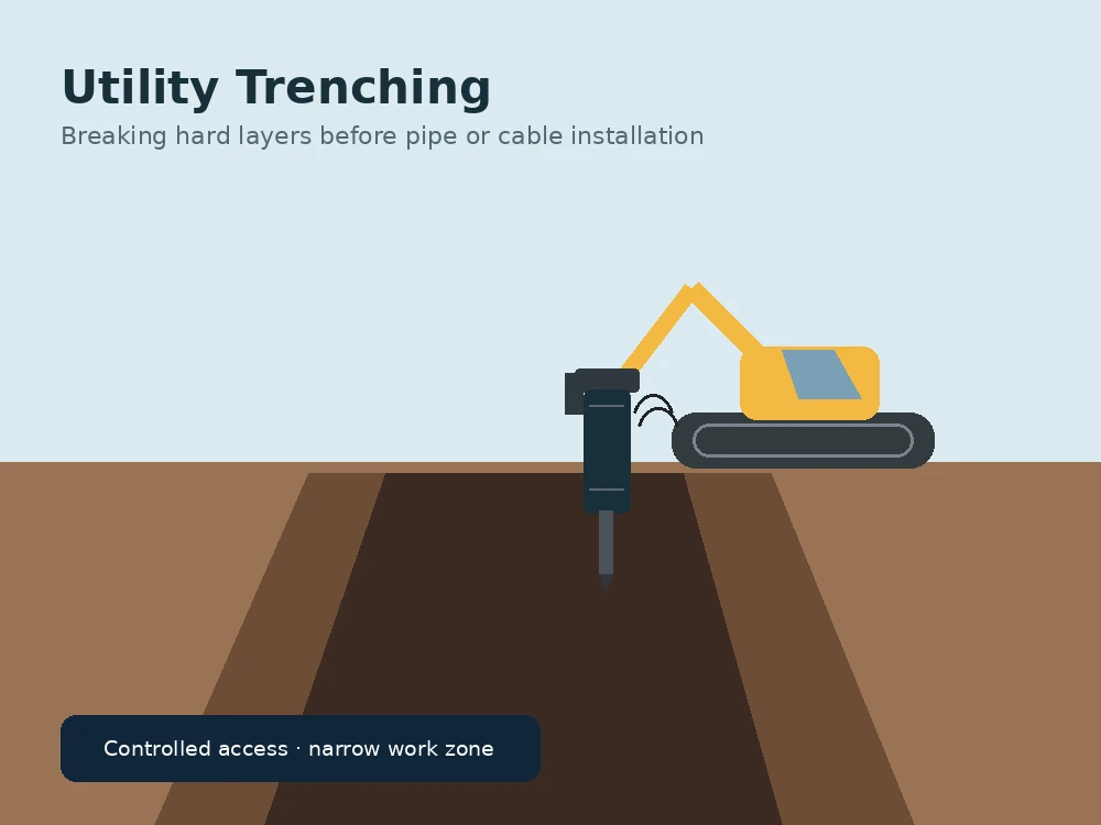
Trenching and utilities
Break rock, concrete or frozen material within a trench alignment where buckets or rippers cannot work effectively.
APPLICATION
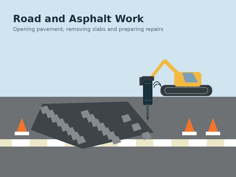
Road and asphalt work
Open pavement, remove damaged surfaces and break concrete around utilities or repair areas.
APPLICATION
Quarry and secondary breaking
Reduce large pieces to a size suitable for loading, crushing or transport.
APPLICATION
Foundation removal
Break footings, piles, bases and other structural concrete during demolition or reconstruction.
APPLICATION
Frozen ground
Open hard frozen layers when approved by the breaker manufacturer and compatible with site conditions.
APPLICATION
Recycling yards
Break concrete and mineral material before crushing, screening or separation.
OPERATING PRACTICE
How to use a hydraulic breaker effectively
Correct positioning improves energy transfer and reduces avoidable stress on the tool, bushings, bracket, hoses and carrier.
AVOID
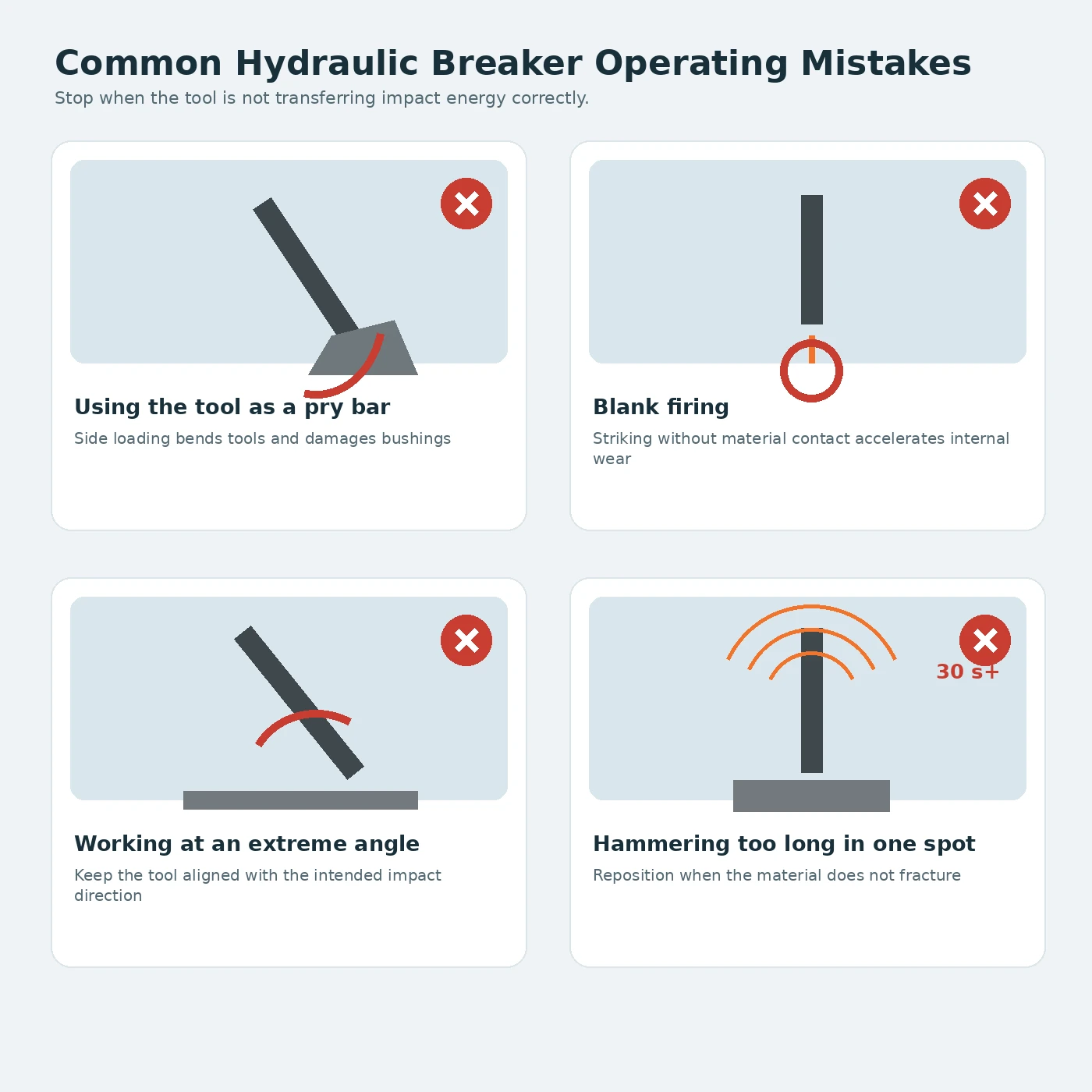
Blank firing
Do not continue cycling when the tool is not firmly loaded against material. Blank firing can create severe internal shock and wear.
AVOID
Using the tool as a pry bar
The working tool is designed to transmit impact. Side loading and levering can bend tools, damage bushings and overload the housing.
AVOID
Working at an extreme angle
Keep the tool aligned with the intended impact direction. Poor alignment increases side load and reduces energy transfer.
AVOID
Hammering too long in one spot
If material does not fracture, reposition the tool. Continuous operation in one location creates heat and can polish the contact point.
AVOID
Lifting with the breaker tool
Do not use the tool or housing as a lifting device unless the manufacturer provides an approved lifting point and procedure.
AVOID
Travelling with the breaker raised
Keep the attachment low during travel and protect hoses, tool and bracket from impact with obstacles.
SERVICE LIFE
Hydraulic breaker maintenance
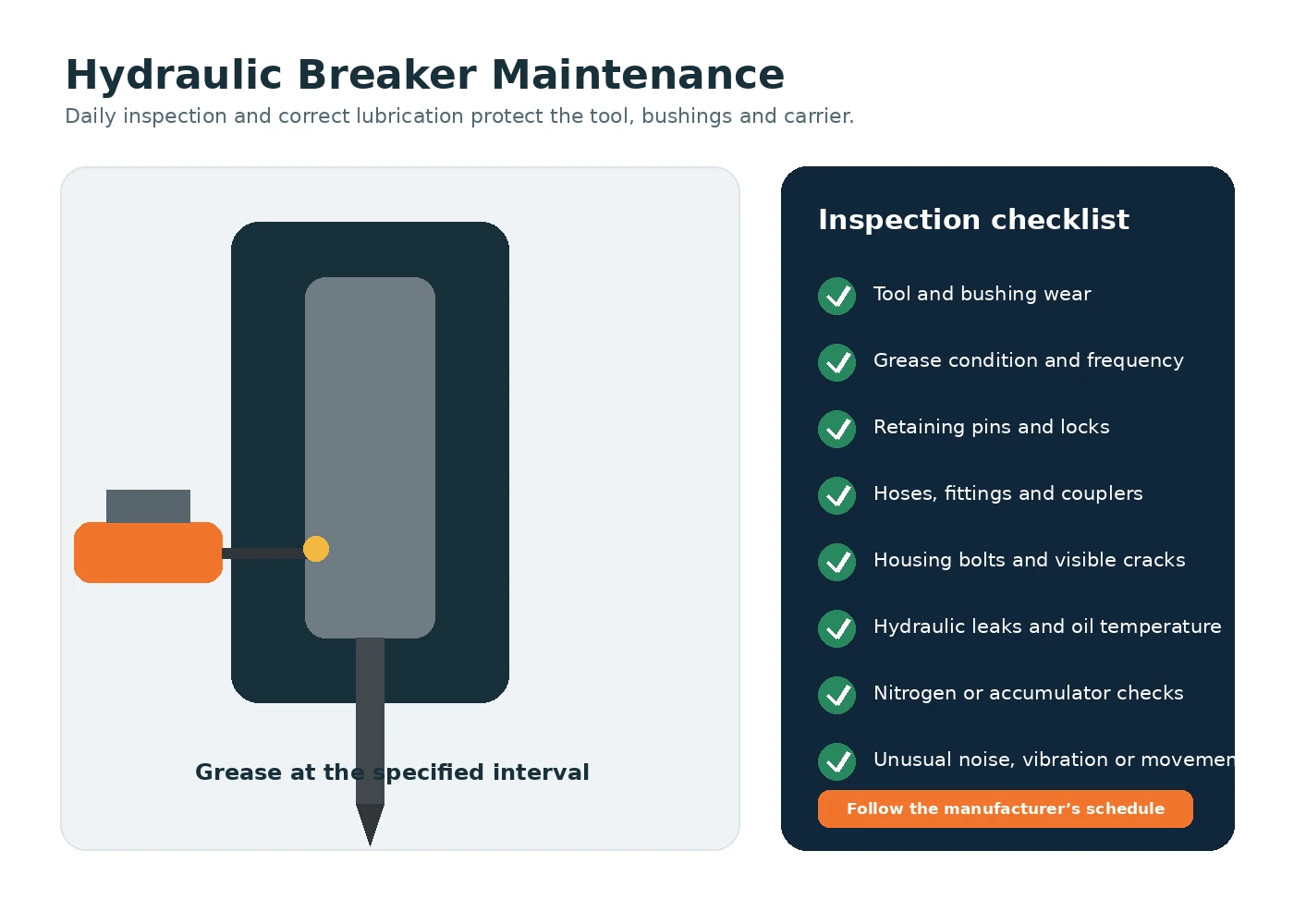
A consistent inspection and lubrication routine is usually cheaper than operating until the breaker loses performance or suffers a major failure.
BEFORE USE
Inspect the mounting and hoses
Check coupler lock, bracket fasteners, retaining pins, hose damage, leaks and clearances before pressurising the circuit.
DURING USE
Grease the working tool
Apply the approved grease at the specified interval and with the tool positioned as required by the manufacturer.
WEAR CONTROL
Measure tool and bushing wear
Excessive clearance increases side loading and can damage seals, piston and tool. Replace parts at the published limit.
HYDRAULICS
Monitor oil and filters
Contamination, overheated oil and blocked filters reduce reliability for both the breaker and carrier.
SCHEDULED SERVICE
Check gas charge and internal components
Only trained personnel should service accumulators, gas chambers, seals and internal breaker components.
STORAGE
Protect the breaker when parked
Clean the tool area, relieve pressure, cap disconnected hoses and store the breaker according to the manufacturer’s instructions.
| Interval | Typical checks | Action |
|---|---|---|
| Before each shift | Mounting lock, hoses, leaks, tool, retaining pins and visible fasteners | Correct defects before operation |
| During operation | Grease supply, oil temperature, unusual noise, hose movement and tool alignment | Stop and investigate abnormal conditions |
| Regular inspection | Tool diameter, bushing clearance, bracket wear, hose abrasion and fastener torque | Measure against manufacturer limits |
| Scheduled service | Seals, accumulator or gas charge, tie rods, internal wear and hydraulic performance | Use trained service personnel and model-specific procedures |
| Before storage | Cleaning, corrosion protection, hose caps and correct tool position | Store dry and prevent contamination |
FAULT FINDING
Common hydraulic breaker problems
Troubleshooting begins with safe shutdown, visual inspection and measurement. Do not keep operating a breaker that behaves abnormally.
| Symptom | Possible causes | Next step |
|---|---|---|
| Breaker does not strike | No oil supply, incorrect control setting, excessive back pressure, stuck tool or internal fault | Stop, verify the carrier circuit and consult the breaker manual or service provider |
| Slow or weak striking | Low flow, low pressure, worn tool bushings, incorrect gas charge, hot oil or unsuitable material contact | Measure hydraulic performance and inspect wear before adjusting settings |
| Breaker overheats | Excess flow, restricted return, continuous operation, poor cooling or contaminated oil | Stop operation, identify the restriction and check the cooling system |
| Hoses move violently | Incorrect hose length, poor routing, pressure pulsation, loose clamps or restrictive couplers | Re-route and secure hoses using approved components |
| Tool sticks in the bushing | Side loading, insufficient lubrication, contamination, mushrooming or excessive wear | Stop immediately and inspect the tool and bushings |
| Oil leakage | Damaged hoses, fittings, seals or excessive back pressure | Depressurise safely and repair before operation |
| Frequent tool breakage | Prying, poor alignment, wrong tool type, excessive bushing clearance or unsuitable material | Correct operating technique and verify the tool selection |
BEFORE ORDERING
Hydraulic breaker selection checklist
Use this checklist to collect the information a breaker supplier needs before confirming a model.
- Identify the carrier make, model, operating weight and coupler or pin dimensions.
- Confirm the breaker manufacturer’s approved carrier range.
- Calculate the complete installed attachment weight, including bracket, coupler and tool.
- Measure or verify available auxiliary flow under operating conditions.
- Confirm operating pressure and the carrier relief-valve setting.
- Verify the permitted return back pressure and return-line arrangement.
- Check hose sizes, couplers, pressure ratings and routing.
- Select the working tool for the material and task.
- Confirm noise, vibration, underwater or environmental requirements.
- Check oil-cooling capacity for the expected duty cycle.
- Obtain the correct operator, installation and maintenance documentation.
- Confirm that the carrier and attachment manufacturers approve the intended combination.
SAFE OPERATION
Safety considerations
Hydraulic breakers create flying debris, high noise, vibration, dust and powerful impact forces. Establish an exclusion zone, use appropriate guarding and personal protective equipment, and follow the carrier, breaker and site safety instructions.
Before connecting or servicing hoses, lower the attachment, stop the engine, relieve stored hydraulic pressure and follow the approved lockout procedure. Hydraulic injection injuries require immediate specialist medical treatment.
Never work beneath an unsupported attachment, never modify the bracket or hydraulic circuit without engineering approval, and never assume that a physically compatible coupler proves the combination is safe.
FAQ
Frequently asked questions about hydraulic breakers
These answers provide general guidance. The breaker and carrier manuals remain the controlling sources for a specific installation.
How do I size a hydraulic breaker?
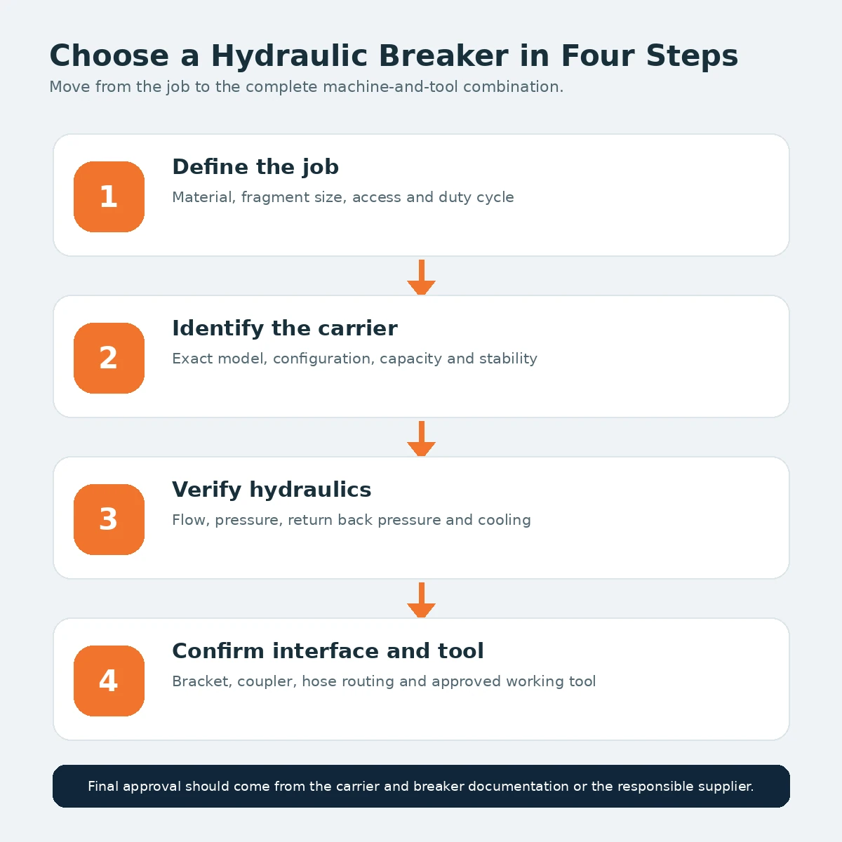
Start with the breaker manufacturer’s approved carrier range, then verify installed weight, auxiliary flow, pressure, return back pressure, mounting interface and the intended material. Do not select solely by tool diameter or impact claims.
Can a hydraulic breaker be too large for an excavator?
Yes. Excess weight and impact loading can reduce stability, overload the boom or coupler and make the machine difficult to control. Use only an approved combination.
What hydraulic flow does a breaker need?
The required flow is specific to the breaker model. Compare the manufacturer’s permitted range with the carrier’s actual auxiliary flow under operating conditions.
Does a hydraulic breaker need a case drain?
Many breakers use pressure and return lines without a conventional case drain, but some models or installations require a dedicated drain or special low-pressure return. Follow the exact installation manual.
How often should a hydraulic breaker be greased?
Use the grease type, quantity and interval stated by the breaker manufacturer. Frequency often increases in dusty, hot or continuous-duty conditions.
Can a skid steer operate a hydraulic breaker?
Yes, when the breaker is approved for the loader and the mount, hydraulic flow, pressure, return path, attachment weight and stability are all suitable.
What causes blank firing?
Blank firing occurs when the breaker cycles without the tool being firmly loaded against material. It can happen after the material fractures or when the operator keeps the control activated while repositioning.
Which breaker tool should I use?
Use a moil point or chisel for penetration and splitting, a blunt tool for broader crushing action, and specialist tools only when approved for the breaker and application.
Why does a breaker become hot?
Common causes include excessive flow, restricted return, long continuous operation, poor carrier cooling, contaminated oil or a hydraulic fault.
Can I use a breaker underwater?
Only with a breaker and installation approved for underwater use. Many systems require an air supply and specific procedures to prevent water and contamination from entering the breaker.
CONTINUE EXPLORING
Related guides and directories
Use these pages to compare the hydraulic breaker with other attachments, machines and applications.
MACHINE GUIDE
Excavator Attachments
Explore the wider range of tools used on excavators and the factors that control compatibility.
MACHINE GUIDE
Skid Steer Attachments
Compare hydraulic and mechanical attachments for wheeled skid steer loaders and compact track loaders.
CATEGORY GUIDE
Demolition Attachments
Browse crushers, pulverizers, shears, breakers and sorting tools for demolition work.
CATEGORY GUIDE
Earthmoving Attachments
Review buckets, rippers, drilling tools, compactors and other ground-working attachments.
DIRECTORY
All Attachments
Browse the master attachment directory and find other individual tool guides.
DIRECTORY
Applications
Start with the job and connect it to relevant attachment and machine families.
NEXT STEP
Match the breaker to the complete machine
Identify the job, carrier, hydraulic circuit, mounting interface and working tool before requesting a model recommendation or quotation.