
INDIVIDUAL ATTACHMENT GUIDE
Demolition Grapples
Types, shell design, rotation, carrier compatibility, hydraulic setup, high-reach work, safety, wear and maintenance.
A demolition grapple is built to grip, pull, strip, separate and place heavy structural debris. The right model must match the carrier, coupler, material, working radius and demolition method—not merely the excavator tonnage.
OVERVIEW
What is a demolition grapple?
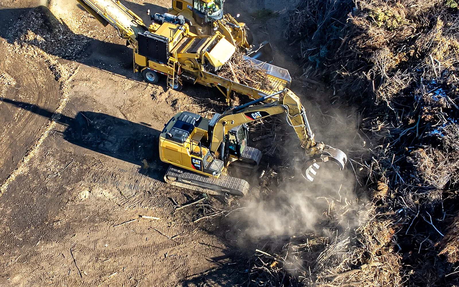
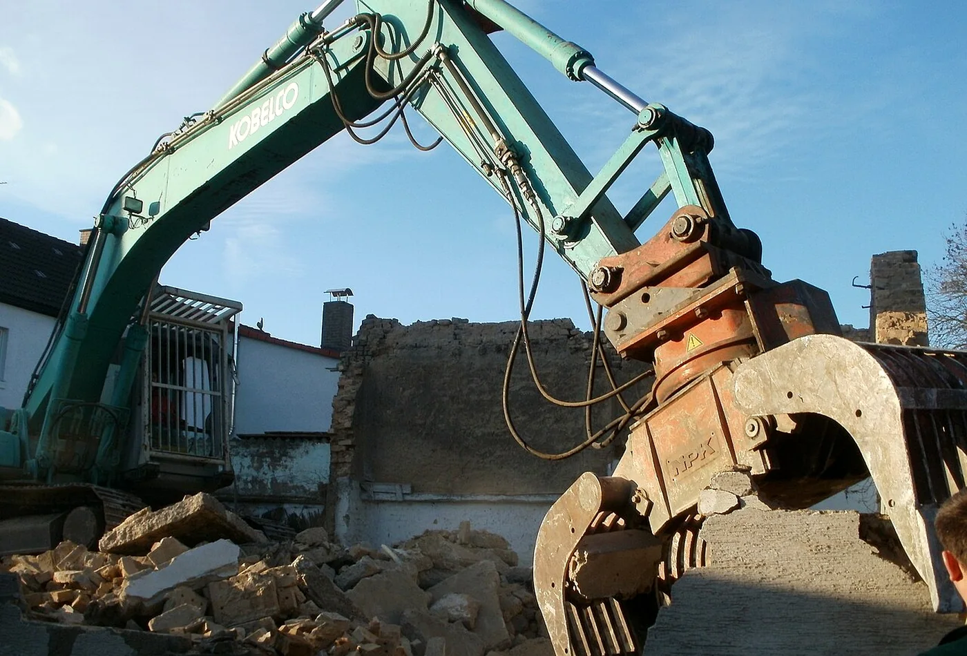
A demolition grapple is a hydraulic excavator attachment with opposing shells or tines that close around structural material. Most dedicated models rotate continuously so the operator can approach beams, slabs, timber, masonry and mixed debris at the safest and most useful angle.
Unlike a bucket, the attachment is designed primarily for controlled gripping and manipulation rather than excavation. Unlike a pulverizer or shear, it generally does not rely on crushing or cutting force as its main function. Its value is precise removal, separation and placement of irregular material throughout the demolition cycle.
Typical functions
- Strip non-structural elements before heavier demolition begins.
- Pull timber, roofing, sheet material, insulation and light framing from a structure.
- Grip and reposition concrete sections after they have been broken or cut.
- Separate reusable or recyclable material from mixed debris.
- Feed crushers, screens, pulverizers or loading areas with controlled placement.
- Clear the work face while keeping personnel outside the machine exclusion zone.
POSITIONING
Demolition grapple or sorting grapple?
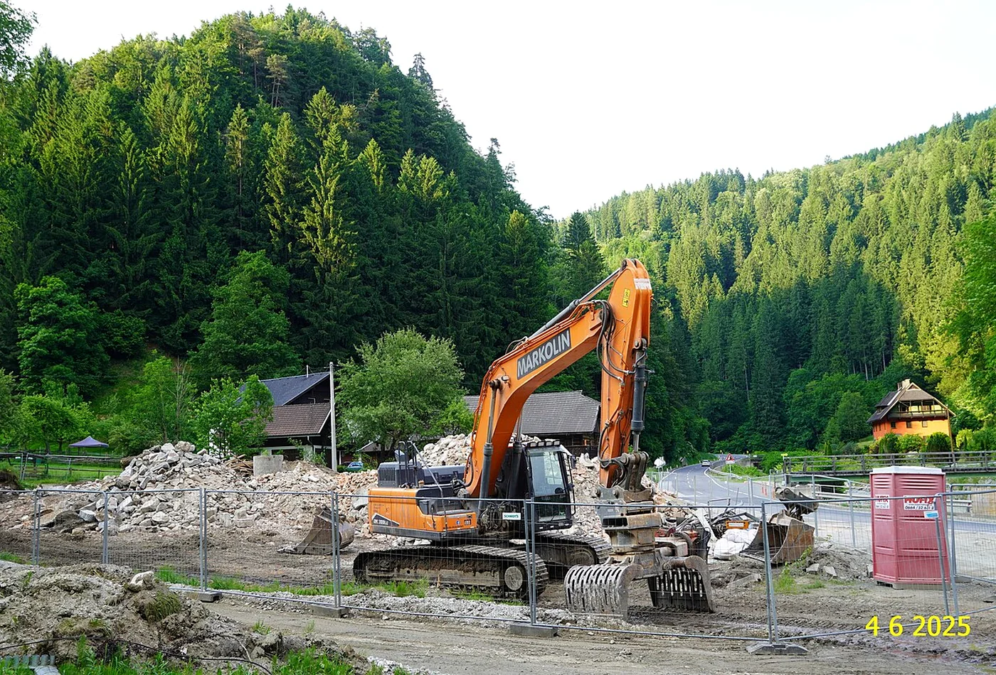
The names overlap, and many rotating selector grapples can perform both jobs. The important distinction is the intended duty. A sorting grapple prioritizes precision, visibility and repeated material separation. A demolition grapple normally adds heavier shell construction, reinforced pivots, stronger edge protection and geometry intended for pulling, prying and handling denser structural pieces.
- Choose a sorting-oriented design for recycling yards, light deconstruction, mixed waste and repeated loading where visibility and low attachment mass are priorities.
- Choose a demolition-oriented design when shells will encounter impact, abrasive concrete, embedded reinforcement and frequent side loading.
- Choose a pulverizer or processor instead when the dominant task is crushing concrete or cutting reinforcement rather than gripping and placing.
- Choose a shear instead for repetitive structural steel cutting where jaw profile and cutting force are critical.
- Choose a breaker instead when mass concrete or rock must first be fractured before it can be handled.
MAIN CONFIGURATIONS
Types of demolition grapples
Manufacturers use different names, so compare the actual shell geometry, installed mass, rotation system and duty rating. The following configurations cover most excavator demolition work.
Heavy-duty rotating grapple
Reinforced shells, protected cylinder and continuous rotation for structural demolition, debris handling and controlled placement.
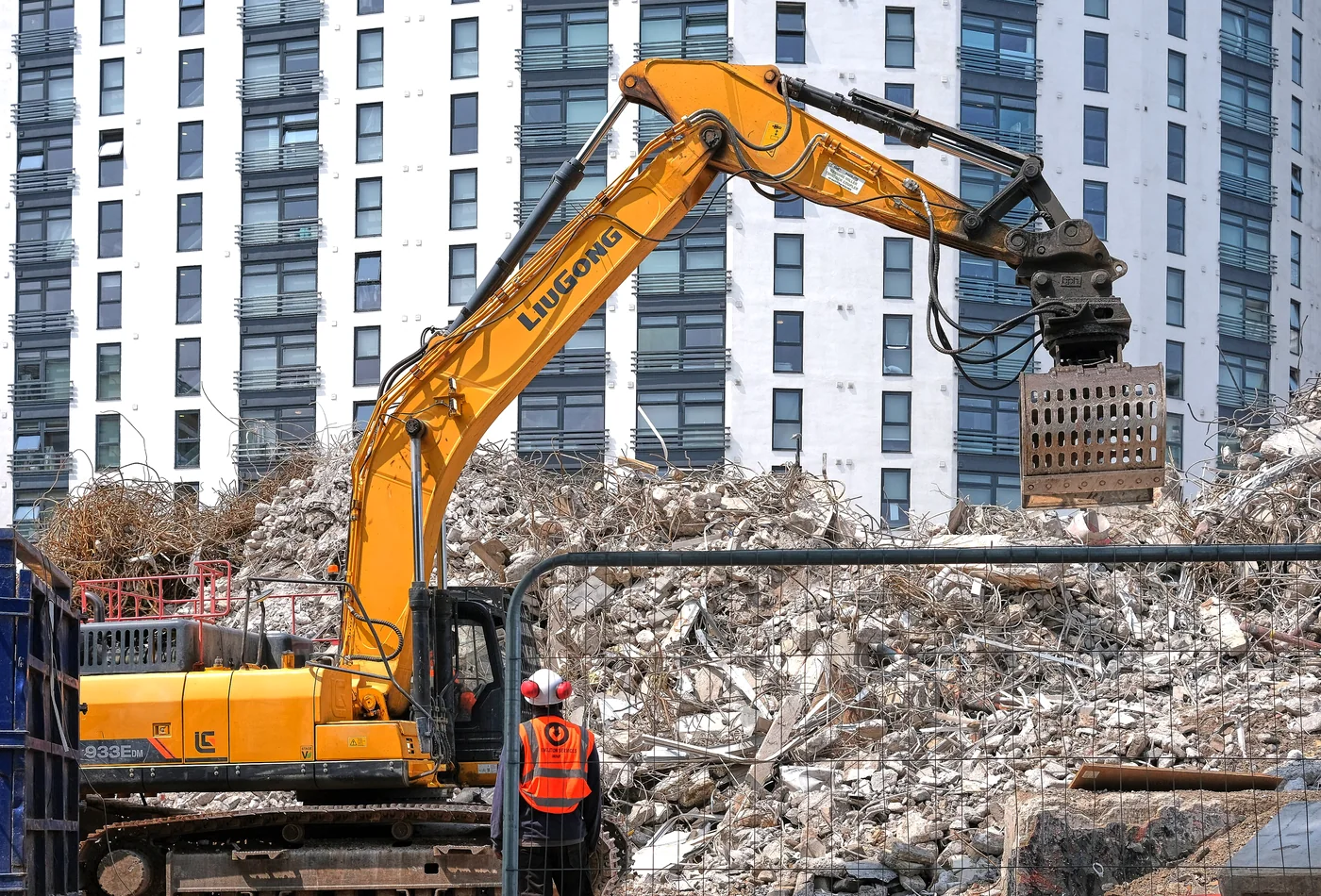
Open skeleton grapple
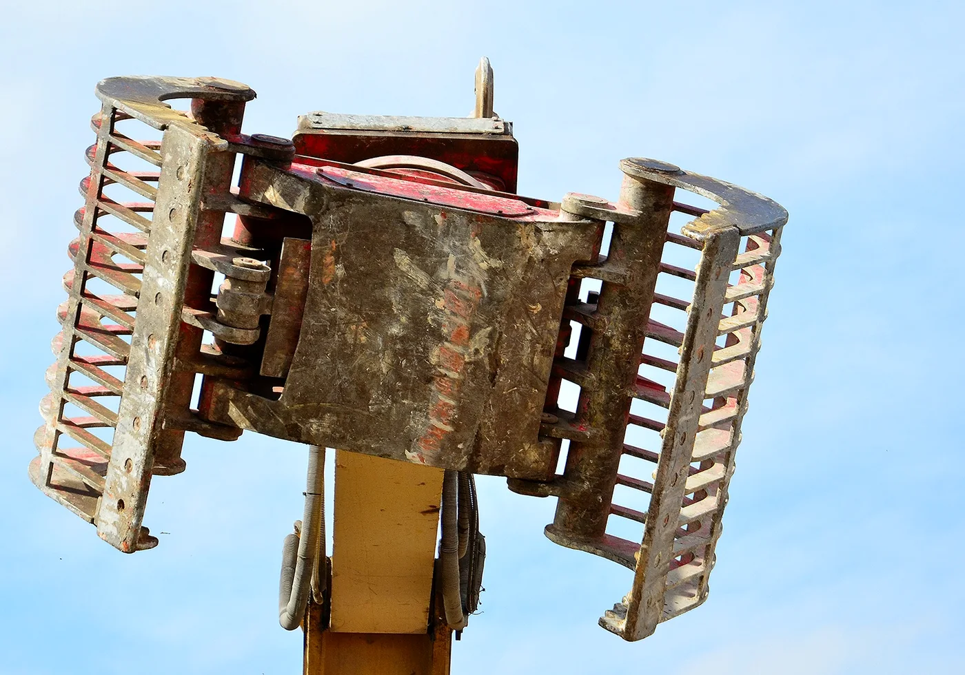
Widely spaced ribs release fines and improve visibility. Useful for sorting mixed debris, timber and larger fragments.
Closed or perforated-shell grapple
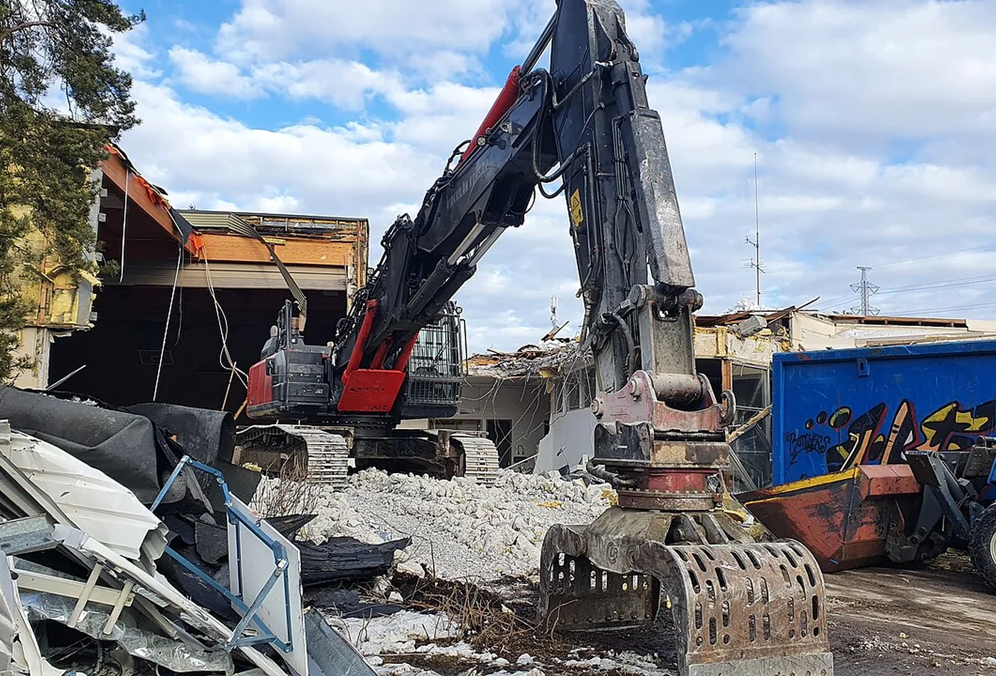
Retains smaller pieces and loose material more effectively, but carries more dead weight and can trap fines.
Tine-style demolition grapple
Narrower contact points penetrate irregular piles and grip beams, roots or bulky material with less shell area.
Fixed grapple
Lower mass and simpler hydraulics where the carrier, tiltrotator or work method already provides sufficient orientation.
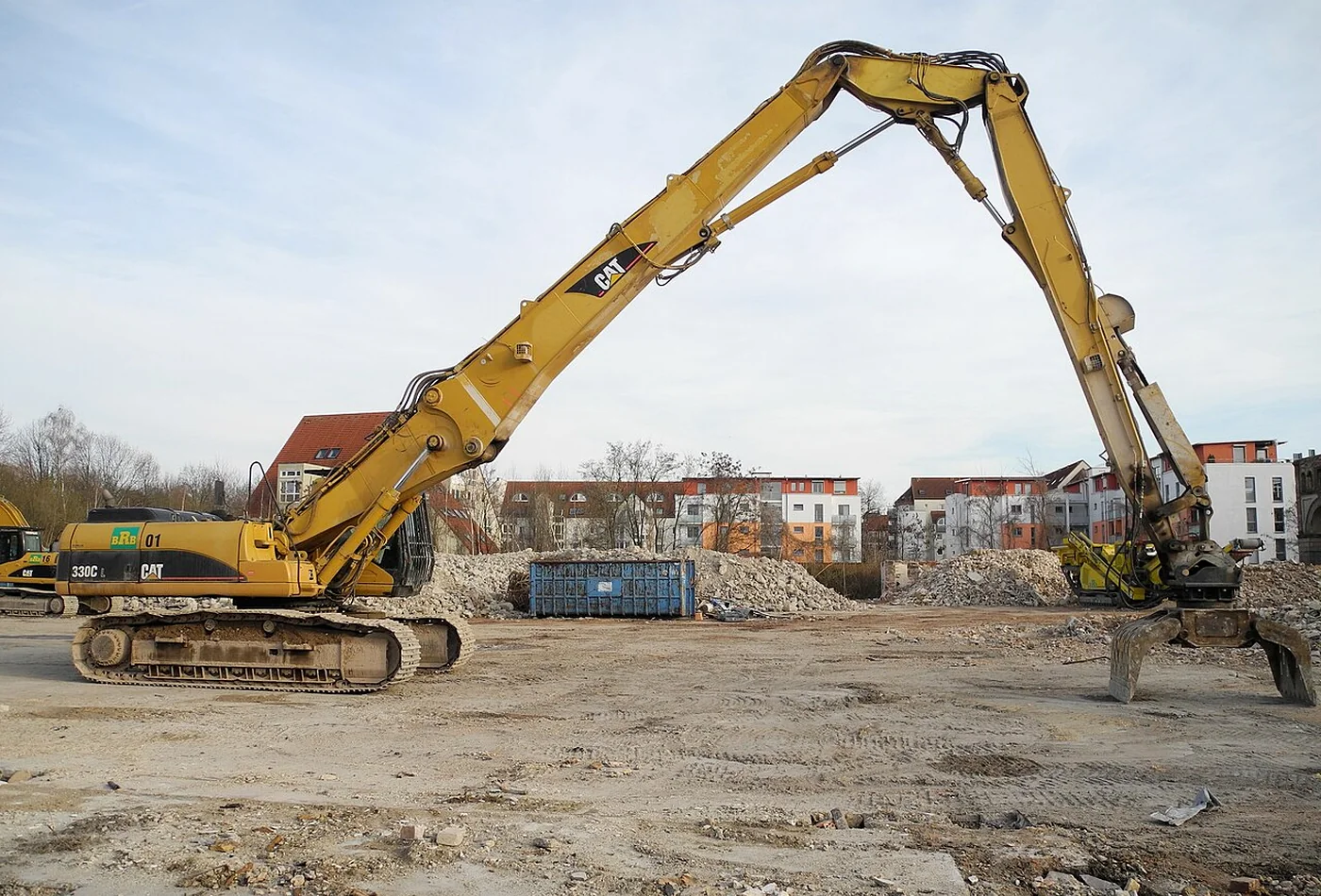
High-reach grapple
Weight-optimized model intended for long-reach carriers, with strict limits on attachment mass, load and working radius.
SHELL SELECTION
Open, closed or tine-style shells?
Open shells improve visibility and allow dust and fines to fall away. Closed shells retain fragments and can move loose debris more efficiently. Tines reach around irregular objects and may reduce contact area, but they are not a substitute for a purpose-built shear or pulverizer. Match the shell to the material stream that dominates the project—not the rare task that occurs once a week.
| Shell style | Best suited to | Main trade-off |
|---|---|---|
| Open skeleton | Mixed debris, timber, steel, large concrete pieces | Small fragments pass through |
| Semi-closed / perforated | General demolition and controlled loading | More weight and less visibility |
| Closed shell | Loose fragments, light bulk material, cleanup | Can retain dirt and increase load rapidly |
| Tine style | Long or irregular objects, selective pulling | Lower bulk capacity and concentrated wear |
DESIGN & LOAD PATHS
The attachment must survive more than closing force
A demolition grapple sees bending, twisting, shock and side loads that are not visible in a simple closing-force figure. Long objects, offset picks and material trapped at one shell tip can create severe leverage through the pivots and rotation assembly.
Components to inspect
- Upper head and adapter: transfers loads from coupler or direct mount into the rotator.
- Rotation bearing: supports axial, radial and overturning loads while allowing orientation.
- Hydraulic motor and valve block: control rotation speed, torque and shock protection.
- Main body and cylinder mounts: resist repeated opening and closing loads without distortion.
- Shell pivots and bushings: carry high local loads and require effective lubrication and replaceable wear parts.
- Edges, tips and side plates: take direct abrasion and should be repairable before base structure is worn.
- Mechanical stops: prevent damaging over-travel and control edge contact or designed overbite.
CARRIER MATCHING
Carrier compatibility is a complete-system calculation
Matching by excavator operating weight alone is not enough. The usable attachment depends on the carrier configuration, boom and stick, working radius, coupler, adapter, optional tiltrotator, counterweight, undercarriage and site position. A combination that is acceptable close to the machine may be unstable or overloaded at full reach or over the side.
Confirm before purchase
- Maximum permitted attachment mass for the exact boom and stick configuration.
- Lift capacity at the actual working radius, height and slew position.
- Total installed mass: grapple, rotator, adapter, coupler, hoses and retained material.
- Pin geometry, coupler standard, pickup width and load-hook requirements.
- Hydraulic flow, maximum pressure, return restrictions and number of auxiliary circuits.
- Transport height, storage position and safe attachment-change procedure.
- Manufacturer approval for high-reach, tiltrotator or quick-coupler combinations.
| Compatibility factor | Why it matters | Practical check |
|---|---|---|
| Installed attachment mass | Consumes lift capacity before material is picked up | Include every adapter and coupler component |
| Working radius | Load moment rises rapidly as reach increases | Check rated lift at realistic boom positions |
| Load center | Long shells and tall adapters increase leverage | Use complete installed height and load position |
| Carrier stability | Side lifting is often the limiting condition | Check over-front and over-side charts separately |
| Hydraulic circuits | Jaw and rotation need controllable independent functions | Confirm proportional control and return path |
| Coupler interface | Adds height, mass and potential movement | Use approved geometry and locking checks |
| High-reach configuration | Permissible tool mass may be much lower | Follow the exact high-reach attachment chart |
HYDRAULIC SETUP
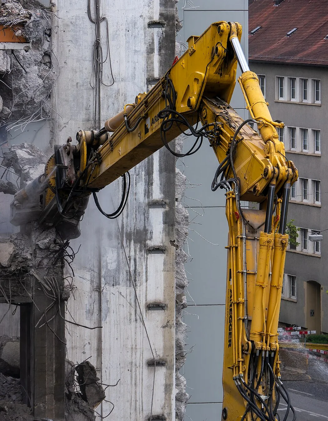
Control, pressure and hose routing
Most rotating demolition grapples need one circuit for opening and closing and another for rotation, unless the carrier uses an integrated control system. Correct settings matter because excessive flow can produce impact at the shell stops, poor modulation and unnecessary heat. Incorrect pressure can damage seals or structure without improving useful grip.
- Jaw circuit: set flow for controllable movement through the full cylinder stroke, not only the fastest open-close time.
- Rotation circuit: use enough flow for accurate alignment; high speed is rarely useful during loaded handling.
- Relief pressure: follow the attachment specification and verify both directions where required.
- Load control: check cross-line relief, anti-cavitation and brake or holding functions in the rotation system.
- Return line: avoid excessive back pressure that increases heat and reduces motor or seal life.
- Hose routing: test full rotation, boom movement and coupler articulation without stretching, pinching or rubbing.
- Commissioning: cycle the empty attachment slowly, then inspect leaks, temperature and control response under realistic loads.
WORK CYCLE
Where demolition grapples add the most value
The grapple is most productive when it replaces repeated manual handling, machine repositioning and uncontrolled dropping. It is a handling and separation tool first, even when the structure is heavy-duty enough for pulling and stripping.
Selective deconstruction
Remove roofing, cladding, timber, fixtures and lighter structural elements in a planned sequence. Rotation helps the operator grip from a controlled angle while keeping the carrier in a stable position.
Secondary demolition and cleanup
Handle pieces after breakers, pulverizers or shears have reduced the structure. Separate concrete, steel, timber and mixed waste before loading or processing.
Feeding and stockpiling
Place material into crushers, screens or containers with controlled orientation. The shell must retain the intended load without exceeding carrier capacity or damaging downstream equipment.
Recovery and salvage
Retrieve reusable components or segregate valuable material where precision is more important than maximum crushing force.
HIGH-REACH DEMOLITION
Low tool weight can matter more than shell volume
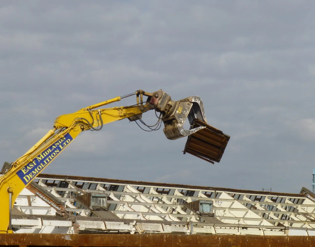
High-reach demolition multiplies the effect of every kilogram at the tool end. A heavy grapple may reduce the carrier’s permitted working envelope, limit the material load or create unacceptable dynamic forces. Use only combinations covered by the carrier’s high-reach chart and attachment approval.
High-reach selection priorities
- Verified tool mass including adapter and hoses.
- Low installed height to reduce load-center distance.
- Adequate grip for controlled removal without unnecessary bulk capacity.
- Rotation torque sufficient for the intended material at working height.
- Secure load retention and smooth proportional control.
- Hose protection against falling fragments and full boom articulation.
- A demolition sequence that avoids pulling unsupported material toward the machine.
Never assume that a grapple approved for a standard boom is automatically approved for a high-reach front. The front configuration, counterweight and permissible tool mass must be treated as one engineered system.
SAFE OPERATION
Plan the exclusion zone and load path
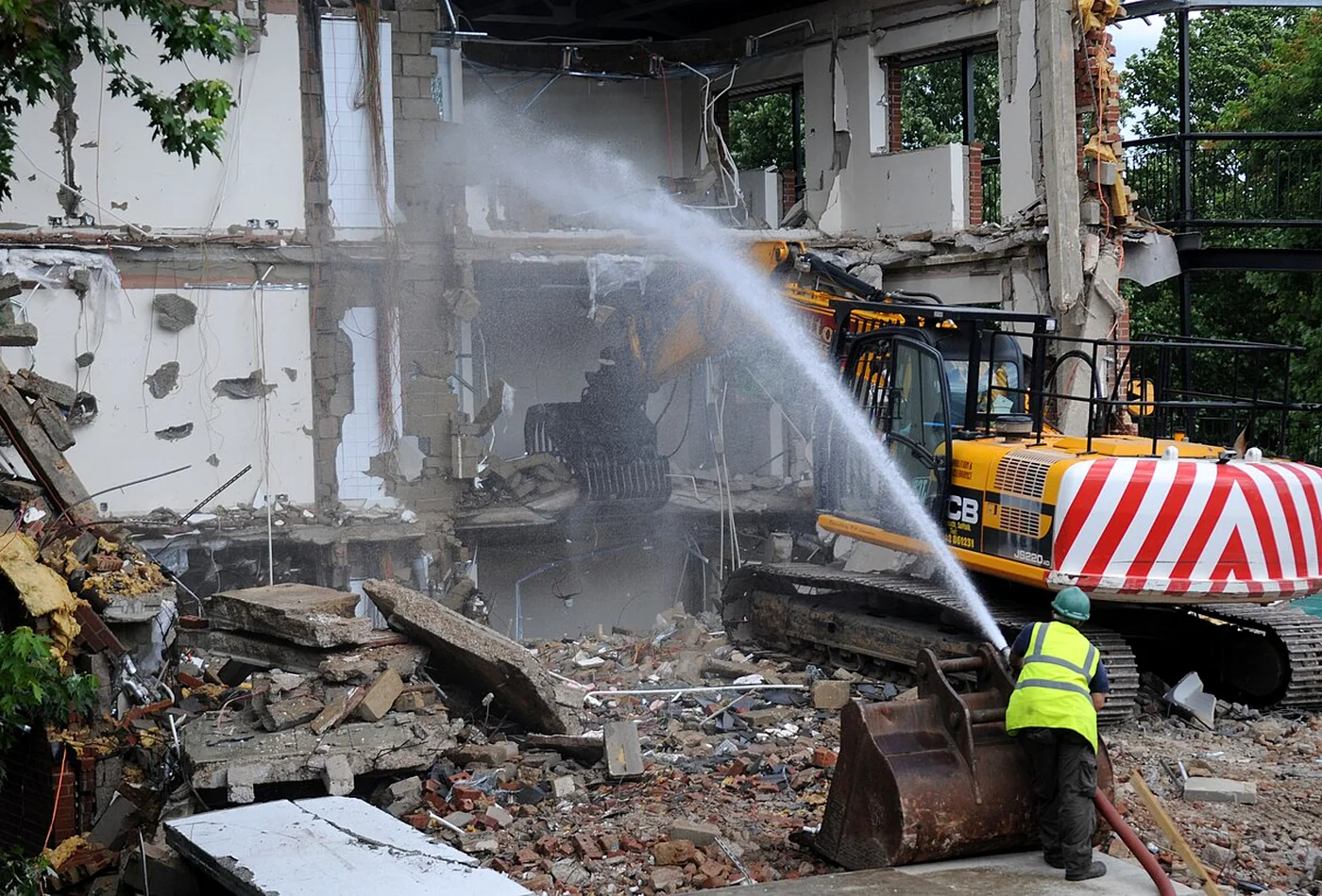
Demolition debris can break, rotate, slide or release stored energy without warning. Safe grapple work depends on the structure survey, demolition sequence, machine position, visibility and communication—not only attachment capacity.
- Establish an exclusion zone for falling material, swinging loads and machine movement.
- Identify utilities, hazardous materials, unstable walls and unsupported structural elements before work starts.
- Approach loads so a sudden release moves away from the cab and carrier where practicable.
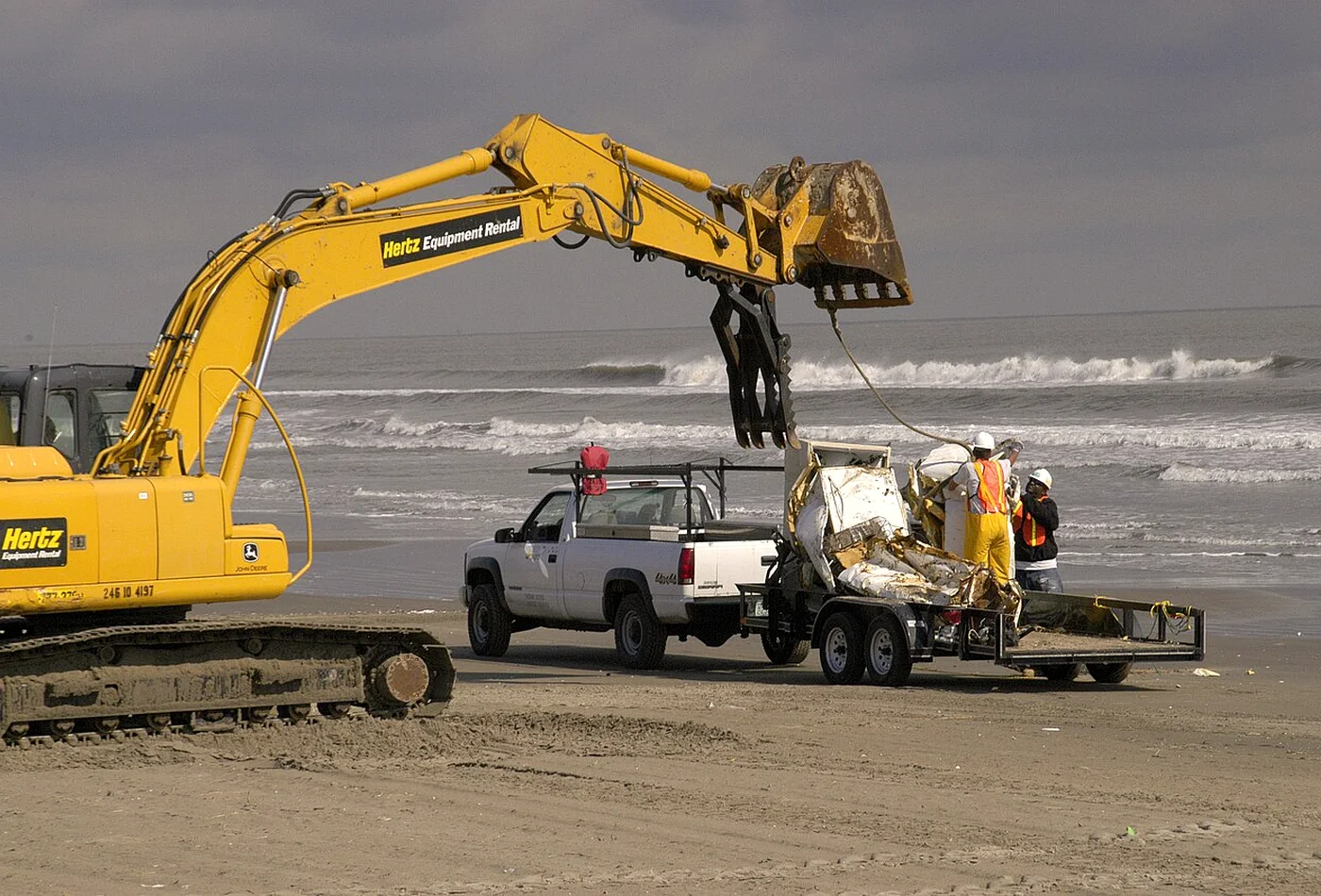
- Do not carry suspended material over people, occupied vehicles or unprotected work areas.
- Keep loads low during travel and avoid side slopes or sudden slewing with a raised load.
- Do not use rotation to tear material when the attachment is not rated for that load case.
- Use screens, guards and cab protection specified for the demolition task.
- Coordinate dust suppression without placing workers inside the attachment or collapse hazard zone.
- Stop if the operator loses sight of the attachment, load or agreed signal person.
HANDLING THE ATTACHMENT
Transport, parking and attachment changes
A grapple that is safe in operation can still create risk when disconnected. Its center of gravity changes with shell position, and a rotating head may allow uncontrolled movement unless the attachment is parked correctly.
- Use the manufacturer’s recommended parking position and a level, load-bearing surface.
- Close or support shells so they cannot move unexpectedly after pressure is released.
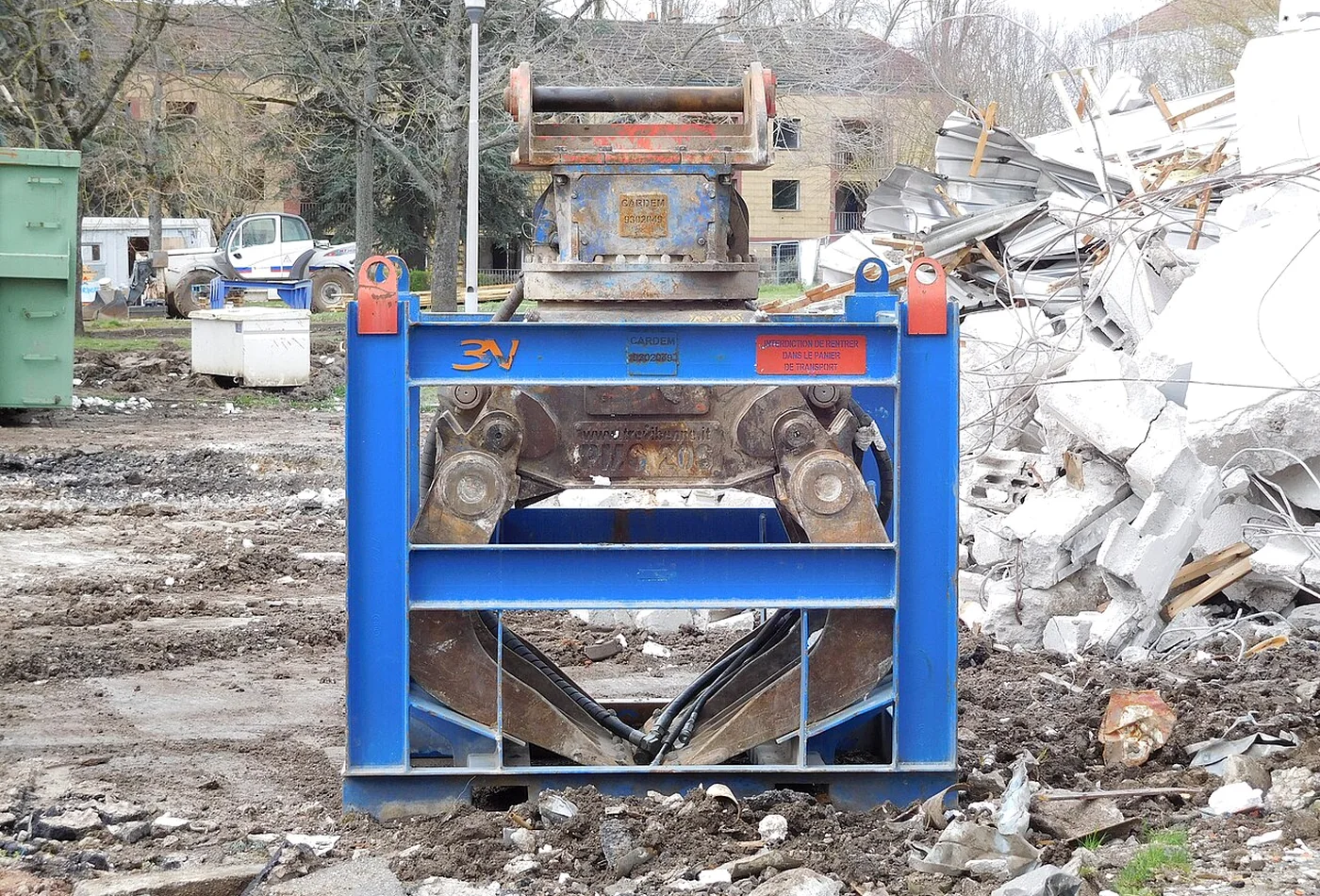
- Use a stable transport or storage frame where the attachment cannot sit securely on its own.
- Relieve hydraulic pressure before disconnecting and protect couplings from contamination.
- Cap hoses, keep them clear of the ground and prevent the rotator from resting on vulnerable fittings.
- Verify coupler lock, safety device and hydraulic connections after every attachment change.
- Perform a low-height function test before returning the machine to the demolition zone.
ATTACHMENT WORKFLOW
Combine the grapple with specialist tools
A demolition grapple rarely performs the whole project alone. The efficient setup uses each attachment for the task it is designed to do, then lets the grapple control material flow between stages.
Typical sequence
- Strip and sort lighter components with the grapple.
- Break mass concrete with a hydraulic breaker or concrete processor.
- Cut structural steel with a shear or multi-processor jaw.
- Use the grapple to remove loosened pieces and expose the next work area.
- Separate material streams before loading, crushing or recycling.
- Finish with a bucket, screening attachment or magnet where the remaining material requires it.
Compare hydraulic breakers or compare sorting grapples before deciding which tool should lead the work cycle.
SERVICE LIFE
Wear points and preventive maintenance
Demolition dust, concrete fines and shock loading quickly turn small clearances into structural wear. A short daily inspection is cheaper than rebuilding oval pivot bores, damaged shell structures or a contaminated rotation bearing.
Daily inspection
Check cracks, loose bolts, oil leaks, hose damage, shell alignment, edge wear and unusual play before work and after any severe impact.
Pins and bushings
Grease at the specified interval and measure play before worn bushings damage the main body or shell lugs.
Rotation system
Inspect bearing clearance, mounting bolts, seals, motor connections and abnormal noise or drift during loaded rotation.
Edges and tips
Rebuild or replace wear components before the base shell plate becomes the contact surface or closing geometry is lost.
Cylinder and valves
Protect the rod from impact, keep pivots aligned and investigate heat, creep or loss of holding force promptly.
Structure and welds
Clean inspection areas and check high-stress transitions, pivot supports, adapter plates and stop blocks for cracking.
Maintenance checklist
- Clean enough debris away to see welds, pins, hoses and bolt heads.
- Confirm shell tips meet evenly and mechanical stops contact as designed.
- Check pivot retaining devices and all rotator-to-body and adapter fasteners.
- Measure edge, tip and side-plate wear against repair limits.
- Inspect hydraulic oil around cylinder seals, swivel joints, motor and valve block.
- Check hose abrasion through full rotation rather than only in the parked position.
- Record developing cracks or play so repair can be planned before the next project.
- After welding or structural repair, follow the attachment manufacturer’s material and procedure requirements.
SELECTION CHECKLIST
Information to collect before requesting a quotation
A useful quotation needs more than the excavator model. Provide the supplier with the complete carrier configuration and a realistic description of the work.
| Information | Examples of what to provide | Why it changes the selection |
|---|---|---|
| Carrier | Make, model, operating mass, boom, stick, counterweight | Defines lift chart and hydraulic availability |
| Mounting | Pin dimensions, coupler brand/type, tiltrotator or direct mount | Controls geometry, mass and adapter design |
| Material | Concrete, brick, timber, mixed debris, steel, bulk waste | Determines shell style, wear package and required grip |
| Largest load | Dimensions, likely mass and where it must be held | Affects opening, leverage and carrier stability |
| Working radius | Typical and maximum reach, over front or side | Determines permitted installed and loaded mass |
| Hydraulics | Flow, pressure, return line, circuits and controls | Determines function speed and compatibility |
| Duty cycle | Hours per day, primary demolition, sorting or cleanup | Determines structure and wear class |
| Site limits | High reach, confined access, transport width, dust and contamination | Changes tool mass, dimensions and protection |
Best practice: ask for the complete installed mass, dimension drawing, hydraulic limits, load or duty guidance, coupler compatibility, wear-part list and maintenance intervals. Compare those values across suppliers rather than comparing nominal carrier classes alone.
FREQUENTLY ASKED QUESTIONS
Demolition grapple FAQ
Can a demolition grapple crush concrete?
It may break small or weakened pieces through gripping and manipulation, but it is not a substitute for a concrete pulverizer or multi-processor. Repeatedly using shell tips as crushing jaws can overload pivots, edges and the rotation system.
Is continuous rotation necessary?
Not always. Continuous rotation greatly improves approach angle and placement, especially without a tiltrotator. A fixed grapple can be lighter, simpler and more robust where the carrier already provides sufficient orientation.
How large should the grapple opening be?
The useful opening must fit the largest regular object at a realistic approach angle. A very large opening usually adds shell size, weight and leverage, so it should not be selected only for rare oversized pieces.
Can the same grapple be used for sorting and demolition?
Many selector grapples can do both. Confirm that the structure, edges, pivots and rotation assembly are rated for the intended demolition duty and that the attachment is not too heavy for routine sorting cycles.
What limits a grapple on a high-reach excavator?
Permitted tool mass, load center, working radius, carrier stability and dynamic loading are usually the key limits. Use the exact high-reach configuration chart and manufacturer approval.
Why does the grapple rotate slowly under load?
Possible causes include low flow, pressure limitation, excessive load moment, worn motor or bearing components, high return pressure or a brake/valve issue. Stop and diagnose rather than increasing pressure without approval.
How often should pins and bushings be greased?
Follow the attachment manual and adjust for dust, water and duty cycle. Demolition frequently requires more attention than general handling. Grease should purge contamination and inspection should confirm that lubrication reaches every bearing.
What is the most common sizing mistake?
Selecting by excavator tonnage or shell volume alone. The complete installed mass, working radius, load density, coupler height and carrier lift chart determine whether the combination is productive and safe.
CONTINUE RESEARCHING
Compare the attachments around the demolition work cycle
Use the demolition hub for the full attachment overview, or compare sorting grapples and hydraulic breakers before defining the next individual guide or purchase specification.